PLF Planetary Speed Reducer

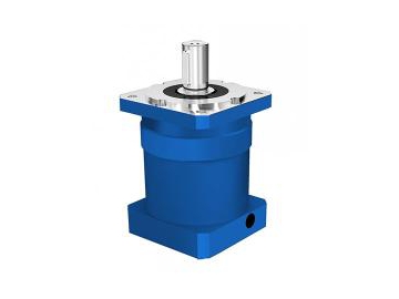

The TQC PLF series speed reducer offers an economic solution for your transmission needs. These gear sets offer high performance transmission at an incredibly low cost. If you have a limited budget and do not required additional transmission features or added torque, this is the gearbox for you.
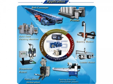
These PLF speed reducers are commonly applied for use in printers, belt conveyers, gantry robots, auto packing and sealing machines, dispenser units, loader robots, etc.
1. Quiet operation
A helical gear allows for smooth and low noise operation.
2. High precision
Accurate positioning is realized with backlash less than 3 arc-min.
3. High rigidity and torque
Rigidity and torque are maximized with the gearbox's single piece roller bearing.
4. Methods of flange and connector
The flange and connector of the gearbox can match with any motor.
5. No leakage of grease
The gearbox is designed for use with high viscosity grease and features non-separated gears to avoid leakage.
6. Convenient maintenance
Grease does not need changing within the service time for easy installation.
We own two multi-national patents for components used in the structure of the inner helical gear to ensure the highest output efficiency.
Patent 1: Reduce the axial thrust caused by the running of planet gears.
Patent 2: Enhanced lubrication provides reduced frictional resistance and noise.
1. ANSYS technology was used to carry out finite element analysis to determine the gear strength. The gear shape and lead of the gear surface are treated in order to minimize noise and impact during gear engagement. This increases the service lifetime of the gears and improves operating efficiency.
2. The gears of the gearbox are made of superior quality alloy steel that has been treated with carbon-nitrogen copermeation to provide maximum wear and impact resistance.
3. The output planet carrier of the gearbox features an integrative design with its double bracing structure. The front and back bearings are distributed along a large span within the box, forming a stable one-piece structure for high torque and precision.
4. The gear ring and output housing are integrated and constructed using high quality hot forged steel, giving the gearbox added strength and durability with additional density. The integrated design ensures the geometric dimensions are accurate and provide maximum precision and strength during operation compared to other structures like built-in and clamp-on units.
5. The design of the input shaft and lock up unit features a uniform distribution to achieve dynamic balance. The double bolts are locked in place to prevent transmission slipping with the motor shaft. Zero backlash is realized.
Prior to choosing a gearbox, specify the gear ratio that you need. After this is selected, multiply the rated torque of the servo motor by the ratio. The value should be less than our gearbox rated output torque, which can be found in the attached data sheets. You should then take the other overloads which drive the motor into consideration to choose the maximum operating torque. This should not exceed 2 times that of our gearbox rated torque.
Once that is decided, you can choose the gearbox with the smallest volume to achieve maximum savings. You can send servo motor dimension drawings for model selection or advise the specific servo motor model number.
If you have any special requirements, please let us know.
1. How to install the gearbox.
Step 1: Wipe off the anti-rust agent and grease on the motor shaft
Step 2: Remove the rubber plug
Step 3: Turn the input shaft until the cap screw is seen. Make sure the cap screw is loosened.
Step 4: Please place reducer vertically on a flat surface, leaving the surface of the motor mounting upwards. Carefully insert the motor shaft into the input shaft (it should insert smoothly). Make sure the motor flange fits perfectly to the reducer flange. Tighten the motor mounting bolt as per appointed fastening torque.
Step 5: Tighten the clamping bolt of the input shaft with a wrench according to the suggested torque.
Step 6: Re-install the rubber plug. Finish the installation.
2. How to store the reducer?
1) Keep the reducer in a clean and dry place.
2) If it will be stored outdoors or in a humid place, please put the reducer in a box packed tightly with a plastic bag to avoid exposure to natural elements. (take any additional anti-condensation and anti-rust measures)
3. Caution for operation:
1) Please confirm the reducer model number is the same as the one you ordered when the reducer is delivered.
2) The reducer was already filled with lubrication oil. You can use it right now.
3) During initial operation, please confirm the rotation direction of the output shaft, then increase the load little by little.
4. Caution during operation:
1) Do not overload!
2) Input speed cannot exceed the proper max. speed.
3) Please stop and check the reducer if any of the following occurs:
Sudden temperature rise
Abnormal noise
Unstable speed
5. Warranty instruction:
The following cost and damages are not included in our warranty:
1) Freight cost
2) If the Reducer connects with or inserts in a unit, when we dismounting or mounting on the unit and other extra action, there will be a cost. (this is not covered in the warranty)
3) The indirect damage that user lost the appliance chance or business break off due to reducer breakdown.
4) Other derivative and accompanying damages.


")


")


