DRV-440E / DRV-443E Side-emitting LED Light Bar
Request a Quote
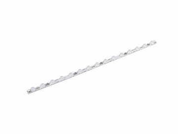
Features:
- Using 3030LED as light source, side-emitting led light bar features low thermal resistance, no light spot, low light decay, and excellent consistency
- Low power consumption, high brightness, long service life, maintenance-free
- Three LEDs cutting interval, attractive and unique appearance, good heat dispersion, suitable for various small size light boxes
- DC24V low power input, safe and reliable, IP33 rated waterproof
- Constant current LED driver
Technical parameters:
| Model | LED chip | Light color LED | Color temperature(K) | Nominal voltage( V ) | Power( W ) | Luminous flux | Beam angle | Dimension | |
| ( LM ) | ( °) | (length*width*height mm) | |||||||
| DRV440E | 3030 | Pure White | 7000-8000 | 24 | 18 | 1800-1900 | 15*45 | 690*19*11.3 | |
| DRV443E | 3030 | Pure White | 7000-8000 | 24 | 25 | 2500-2600 | 15*45 | 940*20*11.3 | |
Dimension (Unit:mm [in]):
Light Distribution Curve:
Connection diagram:
Installation Instructions:
- The main power cable is 2x2.5 mm² or longer. If longer LED Rigid Bar lines are needed, the lamp power must be selected with a wire above 0.75 mm²/ 18 # specifications in order to avoid overloading the power cord. Overloading the power cord leads to excessive heat and dangerous consequences. The switching power supply and power cord length straight between the lamp should not be longer than 3 meters. If longer, the line loss increases with an increase in total power.
- Please use the connection diagram in the wiring scheme.
- The screws in the lamp mounting should be inserted straight into the holes and locked into place; Adhesive backing mounting method is also available.
- If there is exposed wire at the end of LED light bar, the exposed wire should be cut off by diagonal plier and using electrical end cap to seal the wire end for insulation
- To ensure waterproofing and corrosion protection, after the power line is screwed into the terminals, we recommend an injection of a one-component silicone (or otherwise neutral glass, plastic, or waterproof grease) to cover the bare copper wire power cord for additional protection.
- Do not touch the wire after it is installed, as it is a live wire.
- We recommend a switching power supply with the relevant regulatory certification (short circuit protection, overvoltage protection, overcurrent protection).
Installation diagram:
Installation diagram instructions:
- The test panel is a 3mm thick acrylic white board with a light transmittance of approximately 54.4%.
- The experiment uses a metal light box model.
- Arrange evenly according to the photoelectric performance parameters of the product.
Examples of applications: