Monopole Power Transmission Tower


Request a Quote
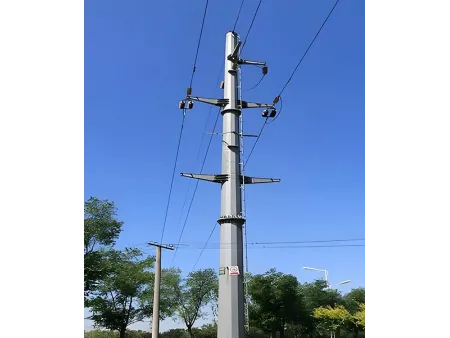
Self-supporting tower with single pole structure for power transmission lines, available in height options from 5 to 60 meters
Monopole power transmission towers use a single tubular steel pole as the main structural element. They are commonly used in urban overhead lines, substation expansions, and wind-power booster stations. Monopoles cost more than angular steel towers to produce, but their long-term maintenance expenses are reduced by about 30%.
- Design Standard ANSI/TIA-222-G/H/F; EN 1991-1-4; EN 1993-3-1
- Height Range 5–60 m, as per customer’s requirement
- Design Wind Speed 0–300 km/h, as per customer’s requirement (varies by region)
- Surface Treatment Hot-dip galvanized
Structural Design
- Tower Structure
The tower structure is formed from a large-diameter steel pole with a 12- to 16-sided cross-section. Using flange or overlap connections for easy transport and installation. - Space Efficiency
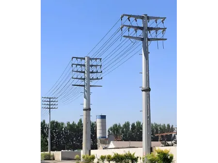
Monopoles require only one-third of the footprint of angular steel towers. They are suitable for narrow urban corridors and areas where land availability is limited. - Wind Performance
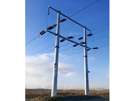
The circular profile provides a lower wind-resistance coefficient. This reduces the wind load on the tower by 40–50% in strong-wind regions, such as coastal zones. - Voltage Range
Monopole towers can support 10 kV to 220 kV transmission lines. Extra-high-voltage applications require larger diameters of 2 meters or more.
Typical Installation Environments
Monopole power transmission towers should be installed with careful consideration of soil conditions, climate, and special environmental factors to ensure long-term stability.
- Plains
Projects in plains require an evaluation of soil firmness. Soft ground should be avoided so the foundation can support both the tower body and conductor tension. - Mountain areas
Sites in mountain regions must avoid geologically weak zones. Stable areas are preferred. Temporary access roads may be needed to handle the complex terrain during construction. - Coastal regions
Coastal projects must account for salt spray, corrosion, and typhoon exposure. The foundation should include moisture-proof and corrosion-resistant measures to ensure reliable performance.
| Product | Power transmission tower |
| Tower Type | Single Circuit Tower, Double Circuit Tower, Multi Circuit Tower |
| Manufacturing Standard | DL/T 646-2012, DL/T 5214-2014, DL/T 5220-2021 |
| Quality Certification | ISO 9001: 2015; COC; Third Party Inspection Report (SGS, BV) |
| Nuts & Bolts | Grade 8.8 / 6.8 / 4.8; A325; DIN 7990, DIN 931, DIN 933; ISO 4032, ISO 4034 |
| Main Material | Q355B Plate steel |
| Height Range | 5–60 m, as per customer's requirement |
| Design Wind Speed | 0–300 km/h, as per customer's requirement (varies by region) |
| Surface Treatment | Hot-dip galvanized |
| Galvanizing Standard | ASTM A123; ISO 1461 |
| Expected Service Life | More than 20 years |
| Color Options | Silver (galvanized) or painted finish, RAL color system, customizable |
| Seismic Resistance | Up to 8° seismic intensity |
| Appropriate Temperature | −60° to 60° |
| Rated Voltage | 10 kV, 33 kV, 66 kV, 110 kV, 132 kV, 220 kV, 380 kV, 400 kV, 500 kV, 750 kV, 1000 kV |
Project Application Examples
- 30-meter Transmission Tower
- 15-meter Transmission Tower
- 22-meter Transmission Tower