AAC Block Production Line

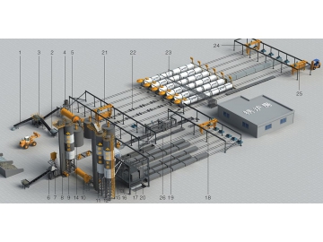
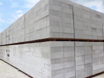
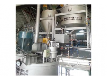

This AAC (autoclaved aerated concrete) block production line uses coal ash (slag or sand) as raw material, lime and cement as cementing material and aluminum powder as foaming agent. The steps of the manufacture procedure of AAC block are smashing, measurement, mixing, pouring, curing, cutting and steam curing. As a new type of wall materials, AAC block is featured with light weight, heat preservation, heat insulation, energy conservation, recycling of waste, eco-friendliness and convenience. With the above advantages, AAC block has become one of the key environment protection projects promoted by the nation.
- (01) Belt Conveyor
- (02) Batching Machine
- (03) Roller Screen
- (04) Grinding Head Silo
- (05) Wet Ball Mill
- (06) Jaw Crusher
- (07) Dust Catcher
- (08) Bucker Elevator
- (09) Silo for Coarse Lime
- (10) Dry Ball Mill
- (11) Silo for Fine lime
- (12) Cement Silo
- (13) Screw Conveyor
- (14) Slurry Storage Tank
- (15) Weighing Hopper for Slurry
- (16) Weighing Hopper for Lime and Cement
- (17) Ferry Cart
- (18) Turning Crane
- (19) Vertical Cutting Machine
- (20) Horizontal Cutting Machine
- (21) Turning & Grouping Crane
- (22) Curing Cart
- (23) Autoclave
- (24) Finished Product Crane
- (25) Block Clamping Machine
- (26) Winch for Side Plate Return
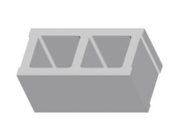
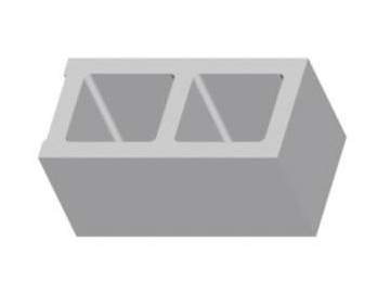
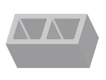
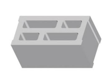
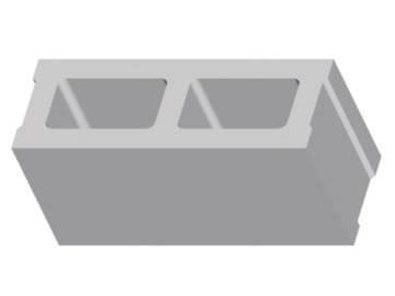
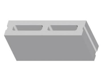
- QFK-1 390x140x190mm concrete hollow block
- QFK-2 390x140x190mm concrete hollow block
- QFK-3 390x140x190mm concrete hollow block
- QFK-4 390x140x190mm concrete hollow block
- QFK-5 390x140x190mm hollow concrete block
- QFK-6 190x190x190mm hollow concrete block
AAC blocks are made using fly ash (lime slag or sand) as the main raw material, cement and lime as the cementing materials, and aluminum powder as the foaming agent. The main forming procedures are as follows: material crushing, measuring, mixing, pouring, curing, cutting and steaming. Not only do the AAC lightweight blocks feature an outstanding heat preservation, energy saving, waste recycling, environmentally friendly and convenient performance, but they are popular all over the world.
AAC Blocks are a new building material that are lightweight, heat retaining and insulated using siliceous (like fly ash) and calcareous materials (like cement and lime) as the main raw material. They are formed through batching, pouring, cutting and steaming. This block type has a production and application history dating back more than 60 years, and is a sophisticated, new building material in terms of both production technology and application s. Due to its excellent light and heat retaining performance, as well as its complementary association to common concrete blocks, it has been widely used in non-bearing walls in industrial construction and civil buildings.
Because the AAC blocks are made of fly ash and lime slag as main raw materials, these blocks are environmentally friendly, with a heat conductivity of about ¼ to 1/5 that of clays bricks. They also feature an outstanding heat retaining and insulation performance, making them ideal building materials for green energy-saving construction, which is also in full compliance with China's strategy for sustainable development.
Light Weight: the dry density is about 1/3 that of clay bricks, and ¼ that of concrete block's. They can effectively reduce the weight and lower construction difficulties for the soft foundations, reduce the foundation and construction investment costs by about 27%, and save 5% on the comprehensive costs.
Heat Preservation: The thickness performance is at 40mm, which is equal to clay bricks with a thickness of 240mm. The heat conductivity coefficient is 0.1w/m.k, making the blocks ideal materials for walls that require self-heat insulation.
Soundproof: There are numerous tiny interior air holes, giving the blocks a double performance of sound and acoustic absorption. The weight-counted sound insulation quantity reaches 40-50dB for different products, thickness and over coatings.
Fireproof: The AAC blocks and raw materials are all inorganic matter, meaning they will never burn and will not produce poisonous gasses at high temperatures. The fire resistance duration of a 100mm thick wall is roughly 4 hours, thus meeting building codes for building fire protection.
Permeability Resistance: there numerous independent closed air holes ranging in diameter from 1-2 mm inside, in order to effectively prevent water diffusion. The permeability resistance is 85% higher than clay brick walls when using traditional, ordinary wall paint.
Strong Rigidity: The precise dimensions, implementation of six surface cutting and usage of a thin mortar layer increases the strength utilization coefficient. The building body strength is 80% of the strength of the block itself, while with a clay brick, it is only 30%.
Economy: The lower light will reduce foundation and construction investment costs. Users can plaster the surface directly, which also saves material and labor costs. The small thickness increases the building utilization coefficient by expanding the usable area. The excellent heat retaining performance also considerably lowers costs.
Precise Dimension: Our advanced manufacturing technique and the equipment ensures the dimension precision is within ±1.5mm margin of error in terms of length, width and height. This is significantly higher than the requirements of other products that meet national standards.
Easy construction: One AAC finished block is equal to multiple clay bricks, which means continuous masonry can be carried out without the limitations of a 1 meter height. This not only increases the masonry speed, but also saves labor costs. The blocks are easy to process, and users can saw, drill, nail, hang or hollow them out, making them ideal for pipe or wire installation and secondary decoration.
Large void and high water absorption rate: There should be no masonry under the standard building height with a ±0.00 margin of error, or exposure to long term moisture, or alternating dry and wet conditions. Users need to use traditional masonry blocks for basic sections, and the height should not be less than 200mm. There should be three layers of the waterproof mortar between the normal brickwork, as well as a waterproof mortar between the brickwork and AAC blocks.
Low Intensity: These blocks are typically used in non-bearing walls where there is no risk of broken corners or crumbling when transferring, two common problems that increase and waste material investment costs.
The surface is easily lathered, and will not easily bond with the mortar. Users need to carry out a sgraffito treatment and add the dula fiber to the mortar before plastering the inner brick wall and priming the outside brick wall.
1. First of all, the raw materials in storage are measured before batching.
2. After batching, the raw material should be fed into pouring mixer for the production of slurry.
3. Pour the evenly mixed slurry into a mould.
4. The half-finished product is ready for cutting only when its hardness reaches a certain degree after pre-curing under a certain temperature and time.
5. Turning crane makes a quarter turn of this mould.
6. The turning crane separates the half-manufactured goods from the mould and place the goods and side plate on the cutting trolley.
7. The cutting machine conducts perpendicular cutting and horizontal cutting on the two sides of the product.
8. Then the cutting machine conducts across cutting on the six surfaces of the half-manufactured goods.
9. The turning & grouping crane removes the base plate of the cut goods and places them together with side plate on the steam curing cart.
10. The products are grouped and put into autoclave for steam curing.
11. Conduct the steam curing of the half manufactured products under certain temperature and pressure.
12. After steam curing, the finished products can be taken out from the autoclave.
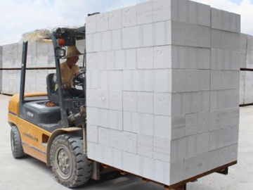
13. The crane places the finished products on the forklift truck, which piles up these products.
14. After package, the finished products are loaded on trucks.
15. The side plate returns along a rail track, combines with a demoulded model frame and thus form a mould which waits for the next slurry pouring.
16. Panel reinforcement (for the manufacture of panels)
AAC block production lines pulverize siliceous material such as sand, fly ash, and other materials. According to raw materials and the process characteristics, the grinding process is as follows: dry grinding into powder, wet grinding with water into slurry and mixed grinding with lime. Mixed grinding can also be classified into a dry mix for preparing plastic material and wet grinding with water. Wet grinding technology with water improves the fly ash or sand characteristics, and is often called "hydrothermal ball smashing".
Typically, most lime types are lump limes, and should be crushed and ground. Gypsum (plaster) is traditionally not ground alone, and fly ash or lime is often added to be ground with the same miller as the lime. Other auxiliary materials and chemicals are often prepared in advance.
The raw material preparation process is the preparatory ingredient process, and is done to meet the raw material technological and processing requirements needed before ingredient completion for the entire production can be carried out smoothly. Product quality will then meet the requirements for all process components, concluding those most basic that have a direct impact.
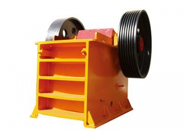
(1) Jaw Crusher
In order to ensure materials meet the technological requirements of aerated concrete blocks, calcareous and siliceous materials are most often ground. Before entering the mill, various bulk materials should first be crushed in order to achieve the feed size required to enter the secondary ball mill grinding.
a. Operating Principle
During operation, through the use of a belt driven eccentric shaft rotation, the motor facilitates the period closing of the movable jaw and periodic jaw fixation, so that materials are squeezed, rubbed, and ground to make them smaller and more easily discharged from the discharge port.
b. Features
The crusher features a large crushing ratio, high yield, uniform particle size, simple structure, reliable operation, easy maintenance, economic cost and other advantageous features.
| Model | Max. Feed Size (mm) | Range Output Adjustment (cm) | Capacity (t/h) | Power (kW) | Weight (t) | Overall Dimension (L×W×H) (mm) |
| 125 | 10-40 | 1-5 | 5.5-7.5 | 0.8 | 875×758×850 | |
| 210 | 20-60 | 5-20 | 15 | 2.8 | 1450×1335×1310 | |
| 340 | 40-120 | 15-50 | 30 | 6.8 | 1565×1732×1586 | |
| 300 | 20-100 | 25-70 | 30-37 | 7.3 | 1810×1900×1730 | |
| 125 | 10-40 | 10-40 | 15 | 3.5 | 1430×1635×1108 | |
| 210 | 25-60 | 15-30 | 22 | 4.5 | 1667×1545×1020 | |
| 210 | 25-60 | 20-52 | 30-37 | 6.5 | 1580×1964×1380 | |
| 210 | 25-60 | 25-60 | 37 | 7.7 | 1580×2164×1430 | |
| 250 | 20-80 | 30-90 | 55 | 11 | 1750×2320×1730 |
(2) Bucket Elevator
Bucket elevators are indispensable equipment in an AAC production line. They are used to carry lime, gypsum and other materials that have been pulverized using jaw crusher to the storage silos, where they are then prepared for raw material mixing.
a. Operating Principle
An NE bucket elevator consists of operation parts (bucket and traction belt), upper parts with a transmission drum, bottom parts with a tension roller, middle enclosure, actuating device, and braking device. It is used to convey powders that are of a loose density (ρ<1.5t/m), and particulates or blocks such as coal, sand, breeze, [GF2] cement and broken ores.
b. Main Features
An NE Bucket elevator uses a flow-through feeding method. Material will be conveyed to the top via a Plate-Link chain, then discharge through a gravitational pull. These elevators are multi-standard, and feature a high production capacity and low energy consumption. They are designed as totally-enclosed with a slow-running chain, which avoids material returning, thus preventing any power waste. There is also no noise pollution.
| Model | Productivity (m³ /h) | Working Speed (m/s) | Main shaft Speedr.p.m | Particle Size (mm) | Bucket Specification | ||
| Volume(L) | Width(mm) | Bucket Distance(mm) | |||||
| 15 | 0.5 | 15.54 | < 40 | 2.5 | 250 | 203 | |
| 32 | 0.5 | 16.45 | < 50 | 7.8 | 300 | 305 | |
| 60 | 0.5 | 16.45 | < 50 | 15.7 | 300 | 305 | |
| 110 | 0.5 | 14.13 | < 70 | 35 | 400 | 400 | |
| 170 | 0.5 | 14.13 | < 70 | 52.5 | 600 | 400 | |
| 210 | 0.5 | 10.9 | < 100 | 84.6 | 600 | 500 | |
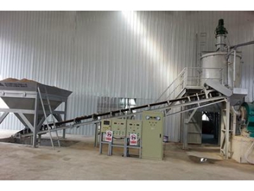
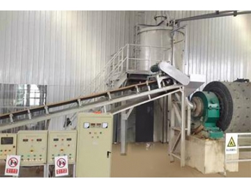
(3) Belt Conveyor
Belt conveyors are key transportation equipment in AAC production lines, as they are used to transport fly ash, sand, lime and other raw materials. They are the most efficient continuous conveyor equipment, as the conveyor belt moves using friction drive principles. Featuring a large capacity, long transmission, smooth transportation, materials and a conveyor with no relative motion, less noise, a simple structure, easy maintenance, less energy consumption and standardized components, our belt conveyors are extremely efficient.
| Belt Width (mm) | Length (m) Power (kW) | Speed (m/s) | Capacity (t/h) | ||
| 500 | ≤12 / 3 | 12-20 / 4-5.5 | 20-30 / 5.5-7.5 | 0.8-1.0 | 50-191 |
| 650 | ≤12 / 4 | 12-20 / 5.5 | 20-30 / 7.5-11 | 0.8-1.60 | 80-250 |
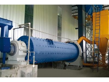
(4) Ball Mill
Raw material grinding is an important step in the AAC block production. Lime, gypsum, sand, slag and other materials are fully mixed and interact only after powder grinding, which is done so to improve product strength. Ball mills are key equipment in material smashing.
a. Working Principle
Ball mills are a horizontal cylinder rotating device that consist of the outer gear, two cabins, and a lattice-type ball mill. Raw materials are evenly fed into the first cabin through a hollow shaft screw. There is ladder liner or corrugated liner inside the first cabin, as well as steel balls in different sizes. When ball mill is operating, the cabin generates centrifugal force, driving the ball to a specific height, after which the ball will fall, leading to a pounding and grinding of materials as the process is repeated. After coarse grinding in first cabin, raw materials will come to the second cabin through a single-compartment plate. There are flat lining and steel balls in the second cabin, which will further grind materials. Finally, powder will be discharged through the discharge grate plate to complete the grinding operation.
b. Structural Features
The machine consists of the feeding part, discharging part, turning part and driving part (reducer, small transmission gear, motors, and electrical control) and other major components. This machine uses an outer gear, hollow shaft support. The hollow shaft features a steel casting and removable liner. The turning gearwheel machining uses casting hobbling, and wear liners are embedded in the cylinder (there are two kinds of liners: rubber liner & steel liners. The rubber liner is light weight, emits little to no noise, and has an excellent sealing and wearing performance). This machine features an excellent wear resistance, as well as smooth, reliable operation.
| Model (m) | Φ1.5×5.7 | Φ1.83×7 | Φ2.2×7 | Φ2.4×8 | Φ2.6×13 |
| Capacity (T/h) | 3.5-4 | 8-12 | 15-17 | 19-22 | 28-31 |
| Max input (mm) | ≤25 | ≤25 | ≤25 | ≤25 | ≤25 |
| Grinding Body | 11T | 21T | 30T | 40T | 78T |
| Power (kW) | 130 | 245 | 380 | 475 | 1000 |
| Weight (t) | 23 | 36 | 49 | 68 | 150 |
(5) Wasted-Slurry Mixing Tank (Ahead of the Ball Mill)
The wasted-Slurry mixing tank consists of a fixing platform, ladder, barrier, mixer and tank. Usually, the wasted slurry from the ferry cart and all other wasted material should be mixed with water in the tank. The mixed material will be recycled, and used in conjunction with the original slurry.
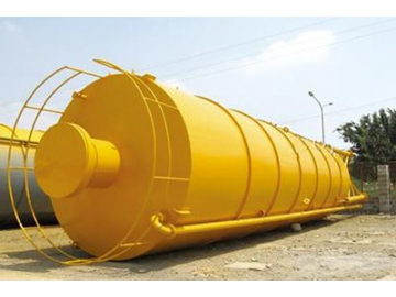
(6) Lime, Cement Silo
The silo role is used for material storage, and is equipped with an air cushion or vibration motor. Based on volume, specifications are 100m ³, 200m ³, and 300m3, and can be configured based on the requirements of select lines. They can be configured according to the demand of select lines.
The dosing is weighted, finished batching materials and all raw materials, whose temperature is adjusted, and concentration and additional materials are added, then, according to the process requirements, fed into the mixer, one at a time. Dosing is a key link of aerated concrete processes, and is related to the raw material between the percentages of active ingredients. It is done to ensure the fluidity and viscosity of slurry is appropriate and whether aluminum powder is suitable for normal gas and green body hardening.
The pouring process is a unique production process for aerated concrete that is different from other types of concrete. The pouring process is the batching process done after measurement and the necessary adjustments are made, in which materials are sent to the mixer for mixing, and done so in accordance with the stipulated time, temperature, and slurry density. Pouring is done through a pouring hole in the mixer, and material flows through the mixer into a mold. Slurry then undergoes a series of physical and chemical reactions in the mold and produces bubbles, which in turn inflate, thicken and harden the slurry. Pouring is an important process for affecting pore structure, and together, the dosing process and pouring process constitute a core part of AAC block production.
Pre-curing processes are the primary process during which slurry continues to harden and thicken after being poured.
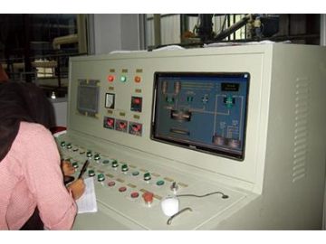
(1) Weighing System
The physical states of raw materials for aerated concrete include liquid, slurry, powder, powdered aluminum and lump aluminum. Different materials have different weighing scales, such as lime scale, cement weighing hopper, slurry weighing tank and more. Material will be precisely measured using the automatic measuring system.
a. Lime & Cement Weighing Hopper:
Used to weigh cement and lime, and then convey them to the pouring mixer.
| Specification (mm) | Length of Screw Conveyor (mm) | Diameter of Screw Conveyor | Speed of Screw Conveyor (r/m) | Weight (t) | Power (kW) |
| Capacity (T/h) | 3.5-4 | 8-12 | 15-17 | 19-22 | 28-31 |
Used to weigh slurry, then convey it to the pouring mixer.
| Specifications(mm) | Wright(t) |
| Ф2000×3000 | 0.8 |
Water measuring and automatic transferal of water to the slurry mixer.
| Specifications (mm) | Wright(t) |
| Ф2000×3000 | 0.2 |
(2) Aluminum Powder Mixer
The aluminum powder mixer consists of the cylinder, a bracket and a pneumatic butterfly valve (double signal output device). It is used to mix aluminum powder.
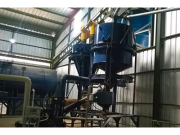
(3) Pouring Mixer
A pouring mixer consists of a mixing barrel, mixing shaft, transmission mechanism, diversion device, and nozzle device. It is the primary equipment in aerated concrete plants. Pouring mixers are used to mix slurry, cement, lime, gypsum and powder aluminum in certain proportions. After uniform mixing and full reaction, the mixed slurry is poured into the mold frame.
(4) Pouring Ferry Cart
Pouring ferry carts are essential equipment in the autoclaved section of an AAC block production line, and are used for dragging. They consist of the cart frame, drive and positioning mechanism. The cart frame is welded using section steel, and the drive consists of the reducer, coupling, shaft, the driving wheel and driven wheel. Ferry carts feature a strong dragging, pushing and stopping power. When quickly moving, they can accurately position and connect, with a slow running frequency when carrying a full load. The frequency running increases when the cart is empty and available to load.
| Ferry cart specifications | Load | Moving speed (frequency) | The distance from cart floor to top | Crat track length |
| m | t | m/min | mm | mm |
| 4.2×1.2 | 6 | 20 | 555 | 3540-5000 |
| 4.8×1.2 | 8 | 20 | 555 | 3540-5000 |
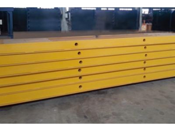
(5) Mold Frame, Side Plate
Molds on an AAC block production line are divided into the mold frame and side plate, and are an important piece of equipment for product formation. The mixed raw materials go through the pouring mixer, and are poured into the mold. They then go through gassing and pre-curing, and after solidification, demolding, and finally, the green block can be cut. The mold frame and side plate are suitable for each of those processes. Simultaneously, side plates take green blocks back to the cutting machine for cutting, and group them into the curing cart, then move them to the autoclave.
The mold frame has an excellent stiffness, as well as easy demolding, no leakage and excellent interchangeability.
The specifications are 4200 x 1200 x 600mm, 4800 x 1200 x 600mm
The side plate has an excellent stiffness, is not easy to deform, durable and features an excellent interchangeability.
The specifications are :4200 x 600, 800 x 600
The turning crane and cutting machine are the two main equipment in AAC Block production plants and are used for block cake cutting and shape processing. The turning & cutting technology features bulk molding, flexible shape and size, and a large mechanization production.
(1) Turning Crane
The turning crane consists of the hanger, rings, rotary lock, and rigging shackle. It is used for block demolding and transferring.
The turning crane overturns blocks at 90°in the air, with demolding subsequently carried out. The separated side plate will combine with the returned mold frame for recycling slurry pouring.
(2) Cutting Machine
The cutting machine consists of a vertical cutting machine and horizontal cutting machine. After pouring, the aerated concrete will form a cake after pre-curing, then the cake will be cut to exact sizes according to user requirements.
Working Principle:
After demolding, the side plate with the block cake will be transferred and attached to the cutting cart, which is then motor driven. The cake then moves to the cutting machine for vertical and horizontal cutting. When cakes arrive at the horizontal cutting machine, the side plate with the cake will be lifted using the lifting device. The cutting cart will then return to its original position and prepare for another round while horizontal cutting is being carried out. After cutting, the lifting device will load the side plate with the cake onto another cutting cart, which will move the cake to the vertical cutting machine for vertical processing.
| Specification | Cake Size After Cutting | Cutting Cycle | Cutting Capacity | Cutting Accuracy | Power |
| m | m | Min/Mold | m³/year | kW | |
| 4.0 | 4×1.2×0.6 | 5 | >100,000 | 3, 1.5, 1.5 | 20 |
| 4.8 | 4×1.2×0.6 | 6 | >200,000 | 3, 1.5, 1.5 | 22 |
(3) Tilting & Grouping Crane
After cutting, the tilting and grouping crane will separate the bottom and top waste by tilting the block cake, then hoist and transfer the cake for grouping.
(4) Grouping Crane
The grouping crane will vertically move the cake with the side plate via the chain. The chain is driven using the oil cylinder, and the crane will horizontally move, driving by a gear motor.
The block cake will be cured in the autoclave. This is the last procedure that directly affects the quality of the finished block.
As the automation improves, the block separating and packing system are also commonly used. After drying, the AAC blocks move out of the autoclaves, and through a hoisting, separating, and packing process, they are transferred to the finished product area via forklift.
(1) Curing Cart
The curing cart consists of a frame and wheel. It is used for transferring the block in and out of the autoclave, which itself is dedicated to the transportation of the cart during production. It sends the cut green block to the autoclave for curing, then moves to the finished product area after curing is complete.
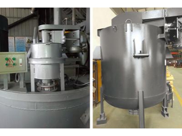
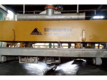
(2) Autoclave
As the core equipment on the production line, an autoclave is used to cure the block under high pressures and temperatures.
| Model | Highest Pressure (Mpa) | Working Pressure (Mpa) | Design Temperature (℃) | Working Temperature (℃) | Working Medium | Door Opening |
| Φ2×21 | 1.4 | 1.3 | 195 | 198 | Saturate Steam | Upward Opening |
| Φ2×26 | 1.4 | 1.3 | 195 | 198 | ||
| Φ2×31 | 1.4 | 1.3 | 195 | 198 | ||
| Φ2.68×31 | 1.6 | 1.5 | 201 | 204 |
(3) Finished-block Clamp
Finished-block clamps are equipped on a special crane. The walking and lifting of these clamps both rely on the crane, and the lifting is oriented using a stable, accurate guide frame. It is specially used for moving finished blocks from the side plate for final packing.
(4) Mobile Separator
The separator is used to separate the finished block in layers. Our separator automatically does the working and grouping of finished products.
(5) Automatic Cuber Crane
The Cuber Crane will cube the finished products after the separating process. It will divide the finished products stack by stack, and after, the tank conveyor will move the stacked block for packing.
(6) Automatic Pallet Provider
Equipped with a block clamping system and tank conveyor, the automatic pallet provider efficiently supplies the pallet for production.
(7) Tank-Type Conveying and Packing System
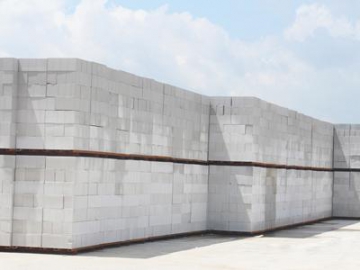
Finished blocks will be packed after the separating and stacking. The packed blocks will be transferred to finished products via forklift.
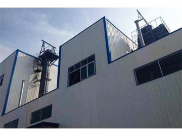
(8) Boiler
The boiler is used to provide heat energy and steam for the autoclave in order to guarantee the interior high pressure and temperature. This ensures the block will complete the hydration reaction for qualified AAC blocks.
Index
autoclaved aerated concrete block, block making machine, lightweight concrete block, construction block


")


