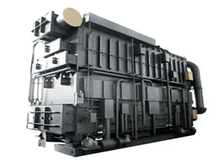
HYTM Hot Water Absorption Chiller


Request a Quote
- Hot Water Temperature Range 80-160℃
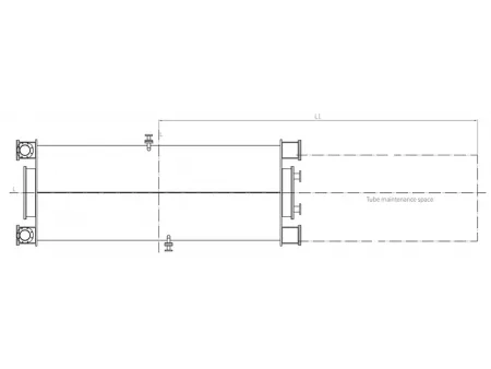
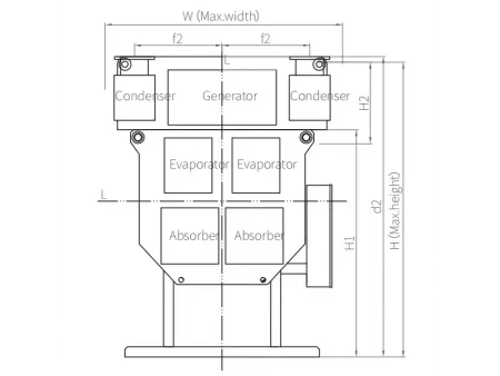
Outline Drawing
- Top view
- Left view
- Front view
- Right view
Working Principle
The HYTM hot water absorption chiller uses water as the refrigerant and lithium bromide solution as the absorbent.
- Inside the evaporator, refrigerant water absorbs heat from the chilled water in heat transfer pipes and become refrigerant vapor, the chilled water temperature is reduced in this process.
- The refrigerant vapor is then absorbed by the lithium bromide solution inside the absorber, where the solution becomes diluted. The diluted solution flows through the heat exchanger into the generator.
- In the generator, hot water supplies heat to the diluted lithium bromide solution, generating refrigerant vapor and increasing the solution concentration. The concentrated solution then returns to the absorber through the heat exchanger for continuous circulation.
Cooling Circle Diagram
Performance Parameters
| Model | ||
| Cooling Capacity | USRT | 120-2646 |
| kW | 422-9305 | |
| 104 kcal/h | 36-800 | |
| Chilled Water Inlet/Outlet Temperature | ℃ | 12 to 7 |
| Cooling Water Inlet/Outlet Temperature | ℃ | 31/32 to 38 |
| Hot Water Inlet/ Outlet Temperature | ℃ | 130 to 70 |
| Power | V/Hz/Ph | 380/50/3 |
| Vacuum Pump | kW | 0.75 |
| Max. Shipping Weight | ton | 57.5 |
Features
Fully Automatic Air Purging System
- The chiller is equipped with a fully automatic air purging system, 3-stage protection of the chiller vacuum.
- The auto-purge system collects the non-condensable gas inside the chiller to the gas tank automatically by the injector. A pressure sensor monitors the pressure inside the gas tank in real time. When the gas pressure reaches the preset value, the vacuum pump will run automatically to purge the non-condensable gas out of the chiller. No manual operation is required during this whole process.
Multilevel Anticrystallization System
- The system monitors the crystallization allowance by the concentration of solution and adjusts the cycle in real time to avoid crystallization.
- The unit is equipped with the automatic crystal melting tube to prevent the crystallization of solution and melt the crystal.
- An optimized dilution running time control function calculates the required dilution running time based on the concentration at shutdown, ensuring safe system shutdown.
VFD Control System
The chiller is designed with a VFD control system for the LiBr solution pump to adjust the LiBr solution recycling volume during part load operation. This design shortens the chiller startup time and improves the chiller efficiency in part load.
Professional Structural Intensity Design
The shell cylinder and water chamber are designed based on stress analysis method, meeting the safety use requirements of the customers in various pressure ranges.
Energy-Efficient Evaporation Absorption Design
- The chiller is designed with double stage evaporation and absorption. Both the evaporator and absorber are divided into high pressure section and low pressure section, the two times of evaporation and absorption improve the chiller efficiency dramatically.
- The evaporator tubes are arranged with non-equal spacing design and copper tubes are used to improve the efficiency of evaporation.
Advanced Gravity Dripping Method
- The solution is dropped and distributed over the tube surface by gravity, eliminating the need for spray pumps and reducing chiller power consumption.
- The solution is distributed in 4 stages to make the entire liquid distribution system more scientific and the liquid film on the heat transfer tube more uniform, improving the absorption and evaporation efficiency.
- The liquid distributor is designed with high-quality stainless steel, never blocked during operation and the chiller life span is much extended.
Piping Flow Chart
Thermal and Cold Insulation
Notes The piping flow is for reference only.
It is recommended to install 10-mesh filter at the chilled water, cooling water pipe, and hot water pipe. The filter should be installed approximately 2 meters from the pipe inlet of the chiller.
It is recommended to install 10-mesh filter at the chilled water, cooling water pipe, and hot water pipe. The filter should be installed approximately 2 meters from the pipe inlet of the chiller.