Aluminum Profile Quench System

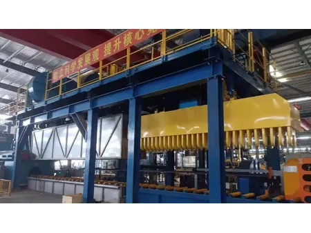
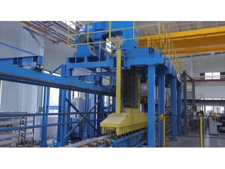
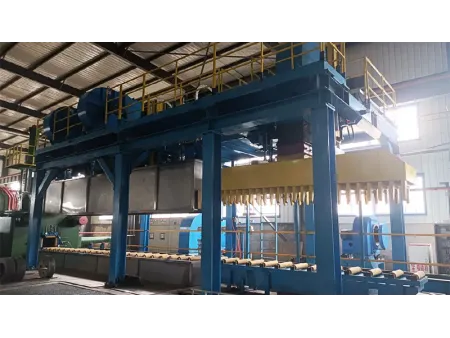
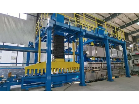
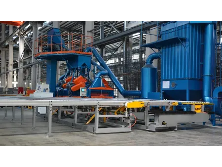

Aluminum Extrusion Equipment
Air and water quench cooling system for increasing the hardness of extruded aluminum profiles
| Quenching Method | Air cooling Water cooling Water mist cooling Water flood cooling | |
| Cooling Section | Total length | 6500mm |
| Lead-out table | 500mm | |
| Air cooling length | 6000mm | |
| Air speed | ≥50m/s | |
| Water spray/mist cooling length | 5000 mm | |
| Water flood cooling length | 4000 mm | |
| Roller | Easily interchangeable (cover material:KAVLAR PBO) | |
| Roller Size | Width | 500mm |
| Pitch | 400mm | |
| Diameter | 96mm | |
The air cooling quench system is based on a 7-meter-long unit with motor-driven elevation and consists of an upper cooling hood and a lower cooling hood.
The upper hood has the following characteristics
- Total fan motor power: 45 kW
- Air volume: 45,000 m³/h
- Divided into three zones:
Top zone: 30 air nozzles, spacing 200mm, size 300mm x 13mm
Left side zone: 30 air nozzles, spacing 200mm, size 150mm x 13mm
Right side zone: 30 air nozzles, spacing 200mm, size 150mm x 13mm
The lower hood has the following characteristics
- Fan motor power: 22 kW
- Air volume: 22,000 m³/h
- Divided into one zone:
Bottom zone: 30 air nozzles, spacing 200mm, size 300mm x 13mm
Additional Features
- Cooling is powered by two independent fans, each controlled by variable frequency drives.
- During non-extrusion cycles, the air cooling system can be shut off using switch valves, conserving energy and extending motor life.
- Both air volume and upper hood height can be adjusted directly via the touchscreen. Cooling configuration settings can be customized for different profiles and stored in the PLC for repeatable use.
- Kevlar rollers in the lower hood are heat-resistant up to 600°C, spaced approximately 400mm apart, and supported by aluminum housings with specialized bearings, allowing operation in humid environments.
- The support system allows height adjustment for precise alignment and quick roller disassembly.
- Roller structure height can be adjusted using a geared motor to align with the extrusion press’s center height. The first roller’s position can be set about 50mm lower than the extrusion press’s centerline.
The water cooling quench system consists of a 5-meter-long independent unit fixed onto a 6-meter structure that is integrated with air-cooling equipment. This unit features several rows of nozzles for effective cooling:
- Upper section: Two rows of nozzles, each with 25 nozzles spaced 200mm apart
- Side sections: One row of nozzles on each side (left and right), each with 25 nozzles spaced 200mm apart
- Lower section: Two rows of nozzles, each with 25 nozzles spaced 400mm apart
Additional Features
- Equipped with a drainage system to prevent freezing and pipe damage during winter.
- Air knives at both the inlet and outlet of the cooling system use compressed air to blow away residual water, ensuring the profiles are fully dried.
- Each section is controlled by proportional valves, allowing water flow adjustment from 30% to 100% of the maximum flow. These valves are managed by the PLC system, enabling different cooling profiles to be tailored for specific profiles. Cooling profile data is stored in the PLC for repeatable use.
- All components in contact with water are made of 304 stainless steel, ensuring durability and corrosion resistance.
- Utilizes air-cooling fans to direct atomized water mist onto the surface of aluminum profiles
- Once the air vents are open, the atomized water mist combines with the airflow to create intense turbulence, ensuring effective and uniform cooling on the surface of the aluminum profiles.
- The water flood cooling quench system features horizontally mounted nozzles with one nozzle at the entry and one at the exit of the cooling channel.
- It is designed to ensure uniform water distribution and effective cooling for the aluminum profiles during the extrusion process.
- When the quench system is in use, the water pump supplies water simultaneously to the two flood nozzles, creating a water trough.
- To use the water trough effectively, both ends of the trough are sealed with wooden boards and fabric pieces to prevent water leakage. The wooden boards and fabric pieces must be prepared by the client.
All water circulation and piping (including the water reservoir) are designed to be placed below the floor near the quenching cooling system. The cooling water circuit is implemented based on the following principles:
- Cooling water reservoir
The client is responsible for constructing the cooling water reservoir according to the seller's design. The reservoir is made of reinforced concrete and installed underground, divided into two separate sections of a cold water reservoir and a hot water reservoir. The total capacity is approximately 25 cubic meters. - Water flow process
Water flows from the quench into the hot water reservoir due to gravity. A pump transfers water from the cold water reservoir to the nozzles. The pump includes a built-in bypass valve to prevent water hammer during the start/stop of the cycle. Water transfer is controlled through proportional control valves, which receive feedback signals from pressure sensors. - External cooling water source and piping
The client is responsible for providing the external cooling water source and related piping. This includes components such as plate heat exchangers, water pumps, and valves. The seller will provide technical specifications for these components, and the buyer will procure them accordingly.
This setup ensures efficient cooling water management while allowing for client-provided external components based on the technical guidance.


")
")


")


")
")


