MRD-ZRK Monitoring Device for Neutral Grounding Resistor
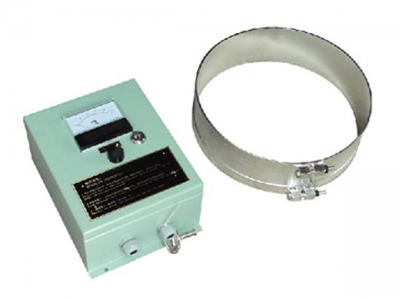
The MRD-ZRK monitoring device for neutral grounding resistor has a quite self-explanatory name, indicating that it could detect and take down many parameters of neutral grounding resistors. With the help of a communication port, our ground fault monitor is able to transfer detection records to the master control room, thus greatly improving the operation safety and reliability of neutral grounding system. In this way, unattended running of substations is realized.

Function
1. Our neutral grounding resistor monitor checks ground fault current, on time, resistor temperature, ambient temperature, ambient humidity, ground connection times as well as other parameters. Then, these data, which won’t be erased even power failure takes place, are delivered to the control room to facilitate people’s work. However, ambient temperature and humidity can be deleted from inspection list if necessary.
2. When grounding current or resistor temperature is higher than the pre-set values, our monitoring device will send out alarm messages.
3. This NGR monitoring device displays corresponding report when ground fault occurs, and it could save failure information of the latest 30 faults.
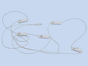
4. Infrared temperature sensors are optional, and they can be adopted to realize contactless temperature measurement for the resistor element.
5. A watchdog timer helps to avoid system crash, and the CT ratio is adjustable.
Connection Schematic of Monitoring Device for Neutral Grounding Resistor| X1 | X2 | ||
| 1 | Grounding Current | 1 | Heating |
| 2 | Grounding Current | 2 | Heating |
| 3 | 3 | ||
| 4 | Sensor (5V) | 4 | Draught Fan |
| 5 | Sensor (GND) | 5 | Draught Fan |
| 6 | Ambient Temperature | 6 | |
| 7 | Ambient Humidity | 7 | Overhigh Ground Current Alarm |
| 8 | 8 | Overhigh Ground Current Alarm | |
| 9 | Resistor Temperature ( ) | 9 | |
| 10 | Resistor Temperature (-) | 10 | Resistor Fault Alarm |
| 11 | 11 | Resistor Fault Alarm | |
| 12 | 485A | 12 | |
| 13 | 485B | 13 | |
| 14 | 14 | AC220/DC | |
| 15 | 15 | AC220/DC- | |
| 16 | 16 | Grounding | |
| Rear Panel Schematic | |||
X1
1, 2: Grounding current connection
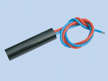
4, 5, 6, 7: Connection ports for ambient temperature & humidity sensor (red line to 5V, black line to GND, white line to ambient temperature, yellow line to ambient humidity)
9, 10, 11: Connection ports for resistor temperature sensor (red line to , black line to -, shield to 11)
12, 13: RS485 communication interface
X2
1, 2: Heating
4, 5: Draught fan
7, 8: Overhigh Ground Current Alarm
10, 11: Resistor fault alarm
14, 15: Power supply
16: Shield
Note: The connections for heating, draught fan, Overhigh Ground Current Alarm and resistor fault alarm are all passive open nodes.


