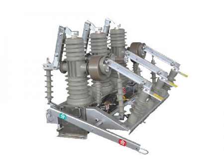
ZW32-12 Outdoor Vacuum Electromagnetic Circuit Breaker
ZW32-12 Outdoor Vacuum Electromagnetic Circuit Breaker
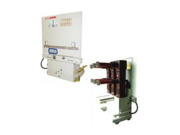
The ZW32-12 outdoor vacuum electromagnetic circuit breaker has a rated voltage of 12 KV.It is a kind of three phase outdoor distribution device for 50 Hz Power. This breaker is mainlyused for the powerdistribution network, and the load current, overload current andshort-circuit current in the electric system. It is also suitable forconstructing and upgrading the power distribution system in cities and ruralplaces, railway system, mining companies, as well as places where frequentoperations are needed, or different kinds of load are handled.
The ZW32-12 outdoor vacuum electromagnetic circuit breaker was developed with the introduction of foreignadvanced technologies, and on the basis of domestic materials and techniques.We have all the intellectual property rights forthis product. It is insulated with combined insulating techniques, while the structure iscompletely sealed. The features include intelligence, greatreliability and small size. Besides, it is also maintenance-free and environmentallyfriendly.
Working environment
Ambient temperature: -45℃~ 45℃
Altitude: ≤ 3000 m
Wind speed: ≤ 34 m/s (equals to apressure of 700 Pa on cylinder’s surface)
Solar radiation intensity: ≤1000 W/m2
Pollution class: Class IV accordingto GB/T5582-1993 (the creep distance of the insulator is 31 mm/kV)
IP rating of the breaker case: IP64
Ice coating thickness: ≤ 10 mm
Seismic capacity: VIII grade(seismic intensity)
Model name and its meaning
:
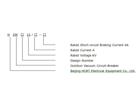
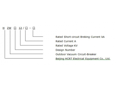
ZW32-12/D630(1250)-20G
Disconnector
(kA)Rated short-circuit breaking current (kA)
(A)Rated current (A)
Electromagnetic operating mechanism
(kA)Maximum working voltage (kA)
Designing series number
Outdoor vacuum circuit breaker
| Main technical parameter | |||
| NO. | Item | Unit | Data |
| 1 | Rated voltage | kV | 12 |
| 2 | Rated current | A | 630,1250 |
| 3 | Rated frequency | Hz | 50 |
| 4 | Rated short circuit withstand current | kA | 20 |
| 5 | Rated short time withstand current | kA | 20 |
| 6 | Rated peak short circuit making current | kA | 50 |
| 7 | Rated peak withstand current | kA | 50 |
| 8 | Secondary circuit power frequency withstand voltage (1 min) | kA | 2 |
| 9 | Thermal stable time | s | 4 |
| 10 | Closing time | ms | ≤ 100 |
| 11 | Opening time | ms | ≤ 50 |
| 12 | Rated lightning impulse peak withstand voltage (phase to phase / phase to earth and across open contacts) | kV | 75/85 |
| 13 | Power frequency withstand voltage (1 min, dry/wet, phase to phase / phase to earth and across open contacts) | kV | (34)42/49 |
| 14 | Mechanism endurance | time | 20000 |
| 15 | Rated operating sequence | Opening-0.3s-closing and opening-180s-closing and opening | |
| 16 | Switch weight | Kg | 70 |
,:
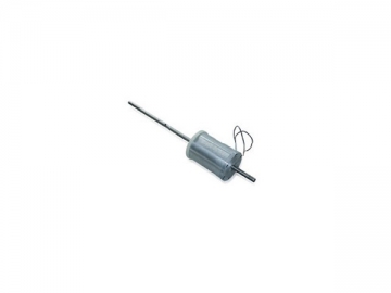
The structure chart of the electromagnetic mechanism
1、 Coil
2、Armature iron
3、Electromagnetic mechanism
4、 Metal case
:
| Technical parameters of the electromagnetic mechanism | |||
| NO. | Item | Unit | Data |
| 1 | Actuator auxiliary power operating voltage | V | AC DC220 |
| 2 | Closing charging time | S | ≤2 |
| 3 | Closing control voltage | V | AC DC 220 |
| 4 | Opening control voltage | V | AC DC 220 |
| 5 | Electromagnet coil temperature-rise | K | 60 |
| 6 | Cable terminal withstand tension (static security coefficient ≥3.2) | N | 500 (lengthways), 250 (transverse), 300 (vertical) |
| 8 | Max. cable charging current | A | 25 |
::
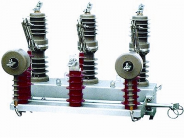
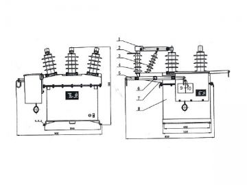
The shape structure chart of the circuit breaker
1- Upper outgoing line
2- Vacuum arc quenching room
3- Insulating silicone rubber
4- SMC SMC insulating material
5- Silicone rubber coat
6- Flexible coupling
7- Spacer flange
8- Insulated brace
9- Silicone rubber coat of theinsulated brace
10- Insulated pull rod
11- Electromagnetic mechanism
12-Pedestal
13-Current transformer
14- Bottom outgoing line
Installation method
::
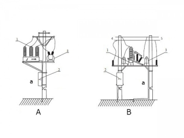
Single pole installing method ofthe breaker
a. Single pole installation
1. Voltage transformer
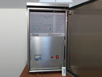
2. Measuring and protectioncontroller
3. Vacuum circuit breaker
Installing method of theintelligent integrated breaker
a. Double pole installation
1. Voltage transformer
2. Measuring and protection controller
3. Vacuum circuit breaker
4.Power side
5.Load side

