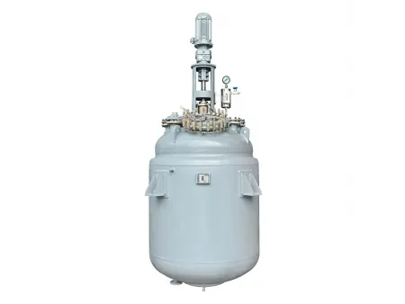
Glass-Lined Reactor, F Type


Request a Quote
Technical Parameters of the Glass-Lined Reactor
F1500L-F6300L Glass-Lined Reactor
F1500L-F6300L Glass-Lined Reactor
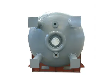
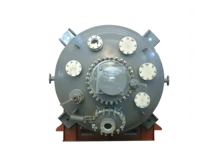
- F1500L- F6300L Design Drawing (Plan View)
| Internal Vessel | Jacket | |
| Design Pressure (MPa) | 0.4 | 0.6 |
| Design Temperature ( ℃ ) | -19 ~200 | -19 ~200 |
| Model | |||||||
| Nominal Capacity (L) | 1500 | 2000 | 3000 | 4000 | 5000 | 6300 | |
| Total Capacity (L) | 2020 | 2470 | 3860 | 4795 | 6040 | 6900 | |
| Calculated Capacity (Note 1) (L) | 1990 | 2440 | 3830 | 4765 | 6016 | 6872 | |
| Jacket Capacity (L) | 301 | 390 | 495 | 805 | 898 | 1015 | |
| Heat Exchange Area (m²) | 5.92 | 7.31 | 9.98 | 12.44 | 14.06 | 16.36 | |
| Half-Pipe Coil Heat Exchange Area (m²) | 2.5 | 3.5 | 4.3 | 6.0 | 7.2 | 8.5 | |
| Reference Weight (kg) | 1975 | 2230 | 3300 | 3750 | 4570 | 5050 | |
| Dimensions (mm) | d1 | 1300 | 1300 | 1600 | 1600 | 1750 | 1750 |
| d2 | 1450 | 1450 | 1750 | 1750 | 1900 | 1900 | |
| d3 (Note 2) | 1915 | 1915 | 2221 | 2221 | 2412 | 2412 | |
| d4 | 680 | 680 | 720 | 720 | 720 | 720 | |
| d5 | 700 | 700 | 800 | 800 | 850 | 850 | |
| h1 | 1801 | 2136 | 2250 | 2730 | 2888 | 3244 | |
| h2 | 190 | 190 | 190 | 190 | 190 | 190 | |
| h3 | 725 | 725 | 700 | 700 | 750 | 750 | |
| h4 | 975 | 975 | 1060 | 1060 | 1200 | 1200 | |
| B1 | 315 | 315 | 315 | 315 | 350 | 350 | |
| B2 | 400 | 400 | 450 | 450 | 500 | 500 | |
| Φ | 30 | 30 | 30 | 30 | 30 | 30 | |
| Vessel Nozzle DN (mm) | a | 300x400 | 300x400 | 300x400 | 300x400 | 300x400 | 300x400 |
| b | 125 | 125 | 150 | 150 | 150 | 150 | |
| C | 100 | 100 | 100 | 100 | 125 | 125 | |
| d | 100 | 100 | 100 | 100 | 125 | 125 | |
| e | 125 | 125 | 125 | 125 | 125 | 125 | |
| f | 125 | 125 | 125 | 125 | 150 | 150 | |
| g | 100 | 100 | 100 | 100 | 125 | 125 | |
| h | 125 | 125 | 125 | 125 | 150 | 150 | |
| 100 | 100 | 125 | 125 | 125 | 125 | ||
| Jacket Nozzle DN (Note 3) (mm) | k1 | 40/50 | 40/50 | 65/50 | 65/50 | 65/50 | 65/50 |
| k2 | 40 | 40 | 65 | 65 | 65 | 65 | |
| k3 | 40/50 | 40/50 | 65/50 | 65/50 | 65/50 | 65/50 | |
| k4 | 40 | 40 | 65 | 65 | 65 | 65 | |
| m | G3/8” | G3/8” | G3/8” | G3/8” | G3/8” | G3/8” | |
| Drive (Note 4) (mm) | dN | 80 | 80 | 95 | 95 | 95 | 95 |
| h5 | 1580 | 1580 | 1680 | 1680 | 1680 | 1780 | |
Notes
- Calculated Capacity
Volume: Measures the capacity below the high neck flange. This does not include the volume taken up by the flange itself. - Support Options
The type of support used to hold the reactor can be specified by the customer when placing an order. If no preference is indicated, the default support type will be lugs attached to the exterior. - k1 and k3 Values
The dimensions k1 and k3 will vary depending on whether the reactor has a full jacket or half pipe heating/cooling system.
For a full jacket, use the values listed before the slash (/)
For half pipes, use the values after the slash (/) - Drive Device Parameters
Reference Only: The provided drive device parameters are for reference purposes.
Actual Selection: The final selection of the rack reducer type will be determined based on the specific requirements of the application.
F8000-F20000L Glass-Lined Reactor
F8000-F20000L Glass-Lined Reactor
- F8000L Design Drawing (Plan View)
- F10000L-20000L Design Drawing (Plan View)
| Internal Vessel | Jacket | |
| Design Pressure (MPa) | 0.4 | 0.6 |
| Design Temperature ( ℃ ) | -19~200 | -19~200 |
| Model | ||||||
| Nominal Capacity (L) | 8000 | 10000 | 12500 | 16000 | 20000 | |
| Total Capacity (L) | 9138 | 11757 | 13733 | 17491 | 21835 | |
| Calculated Capacity (Note 1) (L) | 9110 | 11724 | 13700 | 17446 | 21790 | |
| Jacket Capacity (L) | 1666 | 1940 | 2243 | 2551 | 2870 | |
| Heat Exchange Area (m²) | 18.38 | 21.35 | 24.89 | 29.48 | 34.04 | |
| Half-Pipe Coil Heat Exchange Area (m²) | 8.9 | 10.3 | 12.4 | 14.5 | 16.5 | |
| Reference Weight (kg) | 6780 | 7670 | 9120 | 11300 | 13700 | |
| Dimensions (mm) | d0 | 800 | 800 | 800 | 800 | 900 |
| d1 | 2000 | 2200 | 2200 | 2400 | 2600 | |
| d2 | 2200 | 2400 | 2400 | 2600 | 2800 | |
| d3 (Note 2) | 2763 | 2964 | 2964 | 3238 | 3439 | |
| d4 | 880 | 980 | 980 | 980 | 1080 | |
| d5 | 1100 | 1200 | 1200 | 1200 | 1300 | |
| h1 | 3310 | 3533 | 4053 | 4346 | 4641 | |
| h2 | 210 | 210 | 210 | 210 | 210 | |
| h3 | 850 | 900 | 900 | 950 | 1000 | |
| h4 | 1250 | 1300 | 1300 | 1500 | 1550 | |
| h | 5680 | 5890 | 6440 | 6770 | 7350 | |
| B1 | 400 | 470 | 470 | 470 | 470 | |
| B2 | 700 | 700 | 700 | 700 | 700 | |
| Φ | 36 | 36 | 36 | 36 | 36 | |
| Vessel Nozzle DN (mm) | a | 125 | 150 | 150 | 150 | 150 |
| C | 300x400 | 300x400 | 300x400 | 450 | 450 | |
| d | 200 | 200 | 200 | 200 | 250 | |
| e1 | 200 | 200 | 200 | 200 | 200 | |
| e2 | 150 | 200 | 200 | 200 | 200 | |
| g1 | 150 | 150 | 150 | 150 | 150 | |
| g2 | 150 | 150 | 150 | 150 | 150 | |
| g3 | 150 | 150 | 150 | 150 | 150 | |
| g4 | / | 150 | 150 | 150 | 150 | |
| S | 125 | 125 | 125 | 125 | 125 | |
| k | 125 | 125 | 125 | 125 | 125 | |
| Jacket Nozzle DN (Note 3) (mm) | b1 | 65/65 | 80/65 | 80/65 | 100/65 | 100/65 |
| b2 | 65 | 80 | 80 | 100 | 100 | |
| b3 | 65/65 | 80/65 | 80/65 | 100/65 | 100/65 | |
| b4 | 65 | 80 | 80 | 100 | 100 | |
| m | G3/4° | G3/4” | G3/4 | G3/4” | G3/4* | |
| n | G1/2" | G1/2” | G1/2” | G1/2” | G1/2” | |
| Drive (Note 4) (mm) | dN | 110 | 110 | 110 | 130 | 140 |
| h5 | 1960 | 1960 | 1990 | 2020 | 2300 | |
Notes
- Calculated Capacity
Volume: Measures the capacity below the high neck flange. This does not include the volume taken up by the flange itself. - Support Options
The type of support used to hold the reactor can be specified by the customer when placing an order. If no preference is indicated, the default support type will be lugs attached to the exterior. - b1 and b3 Values
The dimensions b1 and b3 will vary depending on whether the reactor has a full jacket or half pipe heating/cooling system.
For a full jacket, use the values listed before the slash (/)
For half pipes, use the values after the slash (/) - Drive Device Parameters
Reference Only: The provided drive device parameters are for reference purposes.
Actual Selection: The final selection of the rack reducer type will be determined based on the specific requirements of the application.
F30000-F90000 Glass-Lined Reactor
F30000-F90000 Glass-Lined Reactor
- F30000L-50000L Design Drawing (Plan View)
- F60000L-90000L Design Drawing (Plan View)
| Model | ||||||||
| Nominal Capacity (L) | 30000 | 40000 | 45000 | 50000 | 60000 | 70000 | 90000 | |
| Total Capacity (L) | 33645 | 44900 | 51380 | 56470 | 64652 | 75290 | 93110 | |
| Calculated Capacity (Note 1) (L) | 33500 | 44000 | 52180 | 55510 | 63641 | 74300 | 92110 | |
| Jacket Capacity (L) | 3700 | 3800 | 4350 | 4520 | 5080 | 7350 | 9110 | |
| Heat Exchange Area (m²) | 45.0 | 48.4 | 50.2 | 60 | 68.5 | 76.5 | 95.2 | |
| Reference Weight (kg) | 20000 | 26520 | 29650 | 32155 | 36380 | 47950 | 61000 | |
| Dimensions (mm) | d0 | 1100 | 1600 | 1600 | 1750 | 1750 | 1750 | 1750 |
| d1 | 3000 | 3600 | 3600 | 3800 | 3800 | 4000 | 4000 | |
| d2 | 3200 | 3800 | 3800 | 4000 | 4000 | 4200 | 4200 | |
| d4 | 1300 | 1400 | 1400 | 1600 | 1600 | 1600 | 1600 | |
| d5 | 1300 | 1400 | 1400 | 1600 | 1600 | 1600 | 1600 | |
| d6 (Note 2) | 2300 | 2520 | 2520 | 2680 | / | / | / | |
| h1 | 5340 | 5000 | 5731 | 5611 | 6311 | 6692 | 8071 | |
| h2 | 260 | 609 | 609 | 647 | 667 | 667 | 667 | |
| h3 | 1150 | 1300 | 1300 | 1340 | 1340 | 1600 | 1600 | |
| h | 8985 | 9040 | 9770 | 9790 | 10500 | 13000 | 14450 | |
| B | 470 | 470 | 470 | 470 | 470 | 700 | 700 | |
| φ | 24 | 30 | 30 | 30 | / | / | / | |
| Vessel Nozzle DN (mm) | a | 150 | 150 | 150 | 150 | 150 | 150 | 150 |
| C | 450 | 450 | 450 | 450 | 450 | 450 | 450 | |
| d | 250 | 250 | 250 | 250 | 250 | 300 | 300 | |
| e1 | 200 | 200 | 200 | 200 | 200 | 200 | 200 | |
| e2 | 200 | 200 | 200 | 200 | 200 | 200 | 200 | |
| e3 | / | 200 | 200 | 200 | 200 | 200 | 200 | |
| g1 | 150 | 150 | 150 | 150 | 150 | 150 | 150 | |
| g2 | 150 | 150 | 150 | 150 | 150 | 150 | 150 | |
| g3 | 150 | 150 | 150 | 150 | 150 | 150 | 150 | |
| g4 | 150 | 150 | 150 | 150 | 150 | 150 | 150 | |
| S | 125 | 125 | 125 | 125 | 125 | 125 | 125 | |
| k | 125 | 125 | 125 | 250 | 250 | 250 | 250 | |
| Jacket Nozzle DN (mm) | b1 | 100 | 125 | 125 | 125 | 125 | 125 | 125 |
| b2 | 100 | 125 | 125 | 125 | 125 | 125 | 125 | |
| b3 | 100 | 125 | 125 | 125 | 125 | 125 | 125 | |
| b4 | 100 | 125 | 125 | 125 | 125 | 125 | 125 | |
| m | G3/4” | G3/4” | G3/4” | G3/4” | G3/4” | G3/4” | G3/4” | |
| n | G1/2” | G1/2” | G1/2” | G1/2” | G1/2” | G1/2” | G1/2” | |
| Drive (Note 3) (mm) | dN | 160 | 160 | 160 | 180 | 200 | 240 | 273 |
| h5 | 2570 | 2610 | 2610 | 2710 | 3420 | 3970 | 4170 | |
Notes
- Calculated Capacity
Volume: Measures the capacity below the high neck flange. This does not include the volume taken up by the flange itself. - Support Type
Customizable by the user. In the absence of a specific request, B-type support legs will be used. For specifications above F60000L, a skirt support is recommended. - Drive Device Parameters
These parameters are for reference only. The actual rack reducer type will be selected based on specific requirements.
Q630L-Q16000L Glass-Lined Reactor
Q630L-Q16000L Glass-Lined Reactor
- Q630L-Q6300L Design Drawing (Plan View)
- Q8000L Design Drawing (Plan View)
- Q10000L-Q16000L Design Drawing (Plan View)
| Internal Vessel | Jacket | |
| Design Pressure (MPa) | -0.1/0.6/1.0 | 0.6 |
| Design Temperature ( ℃ ) | -19~200 | -19~200 |
| Model | |||||||||||||
| Nominal Capacity (L) | 630 | 1000 | 1500 | 2000 | 3000 | 4000 | 5000 | 6300 | 8000 | 10000 | 12500 | 16000 | |
| Total Capacity (L) | 890 | 1470 | 2130 | 2575 | 3811 | 4780 | 6040 | 6900 | 9105 | 11719 | 13696 | 17491 | |
| Jacket Capacity (L) | 147 | 206 | 301 | 390 | 495 | 805 | 898 | 1015 | 1666 | 1940 | 2243 | 2551 | |
| Heat Exchange Area (m²) | 3.35 | 4.55 | 5.92 | 7.31 | 9.98 | 12.44 | 14.06 | 16.36 | 18.38 | 21.35 | 24.89 | 29.48 | |
| Reference Weight (kg) | 1055 | 1865 | 1963 | 2175 | 3205 | 3522 | 4580 | 5060 | 6718 | 7670 | 9101 | 10954 | |
| Dimensions (mm) | d1 | 1000 | 1200 | 1300 | 1300 | 1600 | 1600 | 1750 | 1750 | 2000 | 2200 | 2200 | 2400 |
| d2 | 1100 | 1300 | 1450 | 1450 | 1750 | 1750 | 1900 | 1900 | 2200 | 2400 | 2400 | 2600 | |
| d3 (Note 1) | 1276 | 1477 | 1655 | 1655 | 1956 | 1956 | 2152 | 2152 | 2452 | 2703 | 2703 | 2908 | |
| h1 | 1385 | 1560 | 1766 | 2131 | 2250 | 2730 | 2888 | 3244 | 3320 | 3543 | 4063 | 4356 | |
| h3 | 595 | 650 | 699 | 699 | 700 | 700 | 750 | 750 | 860 | 910 | 910 | 960 | |
| h4 | 815 | 910 | 940 | 940 | 1060 | 1060 | 1200 | 1200 | 1210 | 1310 | 1310 | 1410 | |
| B1 | 400 | 400 | 400 | 400 | 400 | 400 | 400 | 400 | 400 | 470 | 470 | 470 | |
| B2 | / | / | 510 | 510 | 510 | 510 | 510 | 510 | 510 | 550 | 550 | 550 | |
| Φ | 30 | 30 | 30 | 30 | 30 | 30 | 30 | 30 | 30 | 36 | 36 | 36 | |
| Vessel Nozzle DN (mm) | M | 125 | 125 | 125 | 125 | 150 | 150 | 150 | 150 | 200 | 200 | 200 | 200 |
| L | 100 | 100 | 100 | 100 | 125 | 125 | 125 | 125 | 125 | 150 | 150 | 150 | |
| N1 | 300X400 | 300X400 | 300X400 | 300X400 | 350X450 | 350X450 | 350X450 | 350X450 | 500 | 500 | 500 | 600 | |
| N2 | 100 | 125 | 125 | 125 | 150 | 150 | 200 | 200 | 200 | 200 | 200 | 200 | |
| N3 | 100 | 100 | 100 | 100 | 100 | 100 | 125 | 125 | 150 | 150 | 150 | 150 | |
| N4 | 100 | 100 | 125 | 125 | 125 | 125 | 125 | 125 | 150 | 150 | 150 | 150 | |
| N5 | 100 | 125 | 125 | 125 | 125 | 125 | 150 | 150 | 125 | 125 | 125 | 125 | |
| N6 | 100 | 100 | 100 | 100 | 100 | 100 | 125 | 125 | 150 | 150 | 150 | 150 | |
| N7 | 100 | 100 | 125 | 125 | 125 | 125 | 125 | 125 | 150 | 200 | 200 | 200 | |
| N8 | / | / | / | / | / | / | / | / | 125 | 125 | 125 | 125 | |
| N9 | / | / | / | / | / | / | / | / | / | 150 | 150 | 150 | |
| Jacket Nozzle DN (mm) | N11 | 32 | 32 | 40 | 40 | 50 | 50 | 65 | 65 | 65 | 80 | 80 | 100 |
| N12 | 32 | 32 | 40 | 40 | 50 | 50 | 65 | 65 | 65 | 80 | 80 | 100 | |
| N13 | 32 | 32 | 40 | 40 | 50 | 50 | 65 | 65 | 65 | 80 | 80 | 100 | |
| N14 | / | / | / | / | 65 | 65 | 65 | 80 | 80 | 100 | |||
| N15 | / | / | 50 | 50 | 65 | 65 | 65 | 65 | 65 | 80 | 80 | 100 | |
| N16 | / | / | 50 | 50 | 65 | 65 | 65 | 65 | 65 | 80 | 80 | 100 | |
| N17 | G3/8” | G3/8” | G3/8” | G3/8” | G3/8” | G3/8” | G3/8” | G3/8” | G3/4” | G3/4” | G3/4” | G3/4” | |
| N18 | G1/2” | G1/2” | G1/2” | G1/2” | G1/2” | G1/2” | G1/2” | G1/2” | G1/2” | G1/2” | G1/2” | G1/2” | |
| Drive (mm) | dN | 65 | 80 | 80 | 80 | 95 | 95 | 95 | 95 | 110 | 110 | 110 | 130 |
| h | 680 | 720 | 720 | 720 | 785 | 785 | 785 | 785 | 840 | 840 | 840 | 820 | |
| Notes Support Options: The type of support used to hold the reactor can be specified by the customer when placing an order. If no preference is indicated, the default support type will be lugs attached to the exterior. | |||||||||||||
Related Manufacturies
Leave Message
Similar Manufacturies and Parts
Manufacturer Advertising
Similar Manufacturies and Parts
Videos