Roll Forming Machine
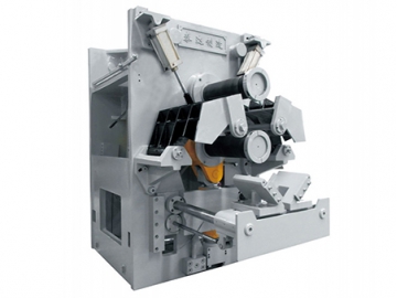
Taizhi’s roll forming machine is specially designed for rim band roll forming and double metal truck brake drum forming. It is primarily used for cold forming of symmetric or asymmetric wheel rims.
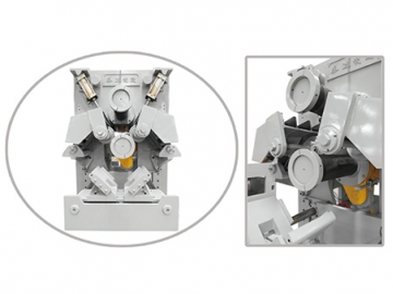
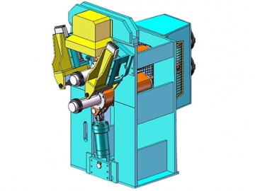
Roll forming includes 3 processes, with each step requiring a roll former. Each roll former is comprised of the main machine, swing upper arm and spindle, swing lower arm and spindle, side guiding device, driver, lubrication system, hydraulic transmission system, pneumatic system, PLC control system, loading and unloading device, and roll forming dies.
Traditionally, small and medium sized wheel rim production lines require 3 processes to for rim profiling completion, with each process requiring at least one roll former. Large wheel rim lines require 4 processes for rim roll forming completion, with the number of roll forming processes depending on the wheel rim design and customer manufacturing requirements.
- The rolling die has an easy-to-disassemble design. A rapid tooling die changing device is also optional, with a quick-change speed of just 30 minutes.
- Both small and large wheel rim lines traditionally use 3 roll forming machines, which share one set of automatic loading and unloading mechanisms to carry out automatic operation.
- The automatic loading and unloading mechanism uses a 3-process and 4-location design, allowing for simultaneous operations that save time and improve production efficiency.
- The automatic loading and unloading mechanism has a split design that matches the roll forming machine. A manual operation line can be dismounted , making it easy to switch between a manual and automatic operation.
- Roll forming dies are designed to be symmetrical or asymmetrical according to your processing demands.
- The upper and lower shafts are hydraulically driven with the speed of both upper and lower rollers automatically adjusted during the forming process.
- The shafts are adjustable in both dip angles and axial directions ensuring each part of the roller surface is evenly stressed, thereby ensuring the processing accuracy.
- The space between the upper and lower spindle is adjustable, as is the feeding speed.
- The side guide rail is adjustable in its stroke.
- Spindle diameter options: 140mm/160mm/180mm/200mm/220mm, according to your processing needs.
- Controller: Mitsubishi PLC and Mitsubishi HMI, or Siemens PLC and HI-TEC HMI
- PLC and module: Mitsubishi PLC and module or Siemens PLC and module
- Spindle adjusting mode: electrical control
- Lower spindle feeding is controlled using a grating scale.
- Hydraulic system oil cooler capacity: 8P 2P
- Range of roll-forming sheet thickness: 2mm~5mm/5mm~10mm
- Adjustable range of spindle in axial direction: ±2mm
- Lower spindle stroke feeding speed: 185mm/s
- Input voltage and frequency: customized to customer requirements.
| No. | Model | Main Parameters | |||
| 1 | Type | GXJ-400 | GXJ-600 | GXJ-800 | |
| 2 | Roll forming force | 230kN | 400kN | 500kN | |
| 3 | Motor power of hydraulic system | 62.5kW | 82.5kW | 165kW | |
| 4 | Length of mold on spindle | 350mm | 670mm | 900mm | |
| 5 | Upper and lower spindle speed | 220r/min | 200r/min | 200r/min | |
| 6 | Spindle material and diameter | 140mm | 200mm | 220mm | |
| 7 | Space between upper and lower spindle | 240~380mm | 340~480mm | 380~520mm | |
| 8 | Lower spindle stroke | 140mm | 140mm | 140mm | |
| 9 | Adjustable range of lower spindle feeding speed | 2~10mm/s | 2~10mm/s | 2~10mm/s | |
| 10 | Adjustable tilting dip angle of lower spindle | -0.34°~ 0.17° | -0.35°~ 0.35° | -0.35°~ 0.35° | |
| 11 | Side guide roller (Linear) | Stroke | 100mm | 140mm | 160mm |
| 12 | Adjustable stroke | 50mm | 50mm | 50mm | |
| 13 | Max. diameter of guide roller | 200mm | 220mm | 240mm | |
| 14 | Rated input voltage | 380V | 380V | 380V | |
| 15 | Rate input current | 62.5kW | 82.5kW | 165kW | |
| 16 | Power cord section (copper) | Single core 70mm² (3 2) | Single core 90mm² (3 2) | Single core 180mm² (3 2) | |
| 17 | Consumption of hydraulic cooling water | 2000L/H | 3000L/H | 4000L/H | |


