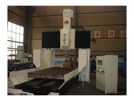
Gantry CNC Drilling-Milling Machine
Request a Quote
The gantry CNC drilling-milling machine is widely used for the drilling and milling of the tube or plate type parts.
Structure- The drilling-milling machine mainly includes machine tool body, workbench, gantry, slide carriage, power head, cooling system, chip removal system, numerical control system, and so forth.
- It adopts the fixed type gantry and machine tool body. But its workbench is movable.
- Both gantry and machine tool body are welded parts. The workbench is made of iron casting. Prior to the processing, all those parts have been treated with high temperature annealing. They have gone through the secondary annealing after the semifinishing. Finally, the finish machining is carried out to ensure the machine precision.
- This CNC machining equipment has three numerical control axles. It is fixed with the heavy linear guide rail, along which the workbench moves longitudinally. Similarly, the gantry crossbeam is also installed with the linear guide rail, and the slide carriage moves horizontally along with this guide rail. On the slide carriage, a slider is mounted. Therefore, the driving head, which is installed with the guide rail, can move along with Z axle on the slide carriage. X, Y, and Z axles are driven by the servo motor together with the ball screw.
- The driving head is equipped with the precision spindle manufactured by the Taiwan Company. Due to the variable frequency motor, it can achieve the stepless speed regulation according to the actual conditions. Additionally, the main shaft is made with the BT40 taper hole, through which it can be connected to the dill, milling cutter.
- Both sides of the workbench are installed with two spiral chip removal devices that work automatically. The machine adopts the water cooling system.
- Our CNC milling drilling machine makes use of the FAGOR8035 system. The system has the RS232 interface, as well as the color display of Chinese version operation interface. The display makes the operation extremely easy.
- The X, Y-axis guide rails together with the guide screw are also equipped with the protective cover. The X axle is equipped with the steel plate shield, and the Y axle is protected by the organ shield.
- To ensure the reliability of CNC machine tool, all the critical parts are imported qualified products. See the attachment for the imported parts.
| Item | Unit | GDC1625D | GDC2030d | GDC2530d | GDC2540d | |||||
| Workbench | Size | mm | 1600 × 2500 | 2000 × 3000 | 2500 × 3000 | 2500 × 4000 | ||||
| Distance Between Columns | mm | 2160 | 2570 | 3210 | 3210 | |||||
| Maximum Allowable Loading | kg | 4000 | 6000 | 10000 | 14000 | |||||
| T-groove Size | mm×number | 22×8 | 22×11 | 28×11 | 28×11 | |||||
| Extended Range | Maxi. Travel of Workbench – X Axle | Without Tool Magazine | mm | 2500 | 3000 | 3000 | 4000 | |||
| With Tool Magazine | mm | 2250 | 2750 | 2750 | 3750 | |||||
| Maximum Travel of Carriage – Y Axle | mm | 1600 | 2000 | 2500 | 2500 | |||||
| Maximum Travel of Main Spindle – Z Axle | mm | 500 | 500 | 500 | 500 | |||||
| Distance Between the Working Surface and Main Spindle End Face | Max. | mm | 650 | 650 | 650 | 650 | ||||
| Min. | mm | 150 | 150 | 150 | 150 | |||||
| Main Spindle | Taper Hole(7: 24) | BT50 | BT50 | BT50 | BT50 | |||||
| No. of Revolution | r/min | 40-4500 | 40-4500 | 40-4500 | 40-4500 | |||||
| Maximum Output Torque | N.m | 385/526 (option dl565/770) | ||||||||
| Maximum Axial Force | N | 15000 | ||||||||
| Motor Power | kW | 15/20.5 × 2 (option dl22/30× 2) | ||||||||
| Maxi. Drilling Diameter | mm | φ50 | ||||||||
| Maxi. Facing Cutter Diameter | mm | φ125 | ||||||||
| Maxi. Tapping Diameter | Cast Iron | mm | M30 | |||||||
| Carbon Steel | mm | M24 | ||||||||
| Feeding | Feed Speed Range For Cutting | mm/min | 1-5000 | |||||||
| Quick Travel | X axle | m/min | 10 | |||||||
| Y axle | m/min | 10 | 10 | 8 | 8 | |||||
| Z axle | m/min | 10 | ||||||||
| Positional Accuracy | JB/T8771.4-1998 | X axle | mm | 0.030 | ||||||
| Y axle | mm | 0.025 | 0.025 | 0.030 | 0.030 | |||||
| Z axle | mm | 0.012 | ||||||||
| JIS Executive Standard(JISB6330) | X axle | mm | ± 0.005/300 | |||||||
| Y axle | mm | |||||||||
| Z axle | mm | |||||||||
| Repositioning Accuracy | JB/T8771.4-1998 | X axle | mm | 0.018 | ||||||
| Y axle | mm | 0.013 | 0.013 | 0.018 | 0.018 | |||||
| Z axle | mm | 0.008 | ||||||||
| JIS Executive Standard (JISB6330) | X axle | mm | ± 0.003 | |||||||
| Y axle | mm | |||||||||
| Z axle | mm | |||||||||
| Machine Tool Weight | kg | 33000 | 37000 | 45500 | 48500 | |||||
| Numerical Control System | Siemens 840D | |||||||||
| Power Capacity | KVA | 90 | ||||||||
