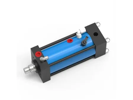
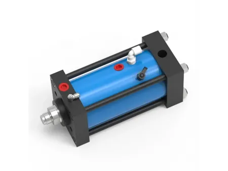
Pneumohydraulic Drive (with Separate Working Cylinder), AT Series


Request a Quote
- Operating pressure ≤6bar
- Pressing force 2-2000kN
- Force stroke 5-52mm
- Total stroke 100/200/250mm
The pneumohydraulic drive combines the advantages of compressed air and hydraulic systems, integrating the high-speed motion of the separate pneumatic cylinder with the high intensity of hydraulic systems. It enables pneumatic rapid advance, pneumatic rapid return, and utilizes the intensifier to provide high-pressure oil to achieve work. The control logic is consistent with standard pneumohydraulic cylinders.
Operating Parameters
| Model | Pressing Force Output (kN, at 400 bar input oil pressure ) | Approach Stroke Force (kg, at 6 bar air pressure) | Return Stroke Force (kg, at 6 bar air pressure) | Oil Consumption per 1mm Stroke (V, CC) | Approach Stroke Oil Loss (V1, cCC, per 50mm) | Hose Expansion/Loss (V2, CC, per 100mm of hose length) | Hydraulic Hose Specification |
| | 13.00 | 95.00 | 105.00 | 0.31 | 0.55 | 0.40 | 3/8" Two-Layer Wire Spiral High-Pressure Hose |
| | 21.00 | 150.00 | 170.00 | 0.49 | 0.70 | 0.70 | 3/8" Two-Layer Wire Spiral High-Pressure Hose |
| | 42.00 | 240.00 | 260.00 | 1.02 | 1.65 | 0.70 | 1/2" Four-Layer Wire Spiral High-Pressure Hose |
| | 81.00 | 350.00 | 370.00 | 1.95 | 3.50 | 0.90 | 1/2" Four-Layer Wire Spiral High-Pressure Hose |
| | 158.00 | 500.00 | 700.00 | 3.85 | 5.00 | 2.00 | 1/2" Four-Layer Wire Spiral High-Pressure Hose |
| | 200.00 | 580.00 | 780.00 | 5.67 | 10.00 | 2.00 | 3/4" Four-Layer Wire Spiral High-Pressure Hose |
| | 320.00 | 730.00 | 1000.00 | 7.85 | 15.50 | 2.00 | 3/4" Four-Layer Wire Spiral High-Pressure Hose |
| | 498.00 | 1150.00 | 1700.00 | 12.27 | 18.50 | 3.10 | 1" Four-Layer Wire Spiral High-Pressure Hose |
| | 1030.00 | 2355.00 | 3780.00 | 25.45 | 36.50 | 3.10 | 1" Four-Layer Wire Spiral High-Pressure Hose |
Cylinder Stroke Parameters
| Model | A1 | B | C | D | E | F (f7) | G | H | K | L | M | N | X |
| | 66 | 320 | 6-M6×12 | 40 | G1/8 | 30 | 10 | 16 | 24 | M12×1.5 | 15 | 13 | G3/8 |
| | 78 | 339 | 6-M08×15 | 54 | G1/4 | 40 | 10 | 20 | 26 | M16×1.5 | 15 | 17 | G1/2 |
| | 98 | 355 | 6-M08×18 | 64 | G3/8 | 50 | 10 | 30 | 29 | M22×2 | 20 | 24 | G1/2 |
| | 120 | 391 | 6-M10×20 | 88 | G1/2 | 70 | 10 | 45 | 35 | M30×2 | 25 | 36 | G3/4 |
| | 145 | 413 | 6-M16×25 | 100 | G1/2 | 75 | 15 | 50 | 36 | M30×2 | 25 | 41 | G3/4 |
| | 166 | 427 | 6-M20×30 | 115 | G1/2 | 85 | 18 | 56 | 52 | M39×2 | 35 | 46 | G3/4 |
| | 190 | 446 | 6-M20×30 | 132 | G3/4 | 100 | 18 | 63 | 47 | M39×2 | 35 | 55 | G1 |
| | 190 | 471 | 8-M20×35 | 150 | G3/4 | 115 | 25 | 63 | 56 | M42×2 | 40 | 55 | G1-1/4 |
| | 315 | 556 | 12-M24×45 | 200 | G1 | 150 | 20 | 100 | 60 | M64×2 | 60 | 85 | G1-1/4 |
Configuration Diagram
- AT Cylinder (Multiple Units) MPSxxx-xxx Intensifier
- AT Cylinder (Multiple Units) TMPSxxx-xxx Intensifier
Cylinder Selection Example
- Requirement: 2 cylinders with 60kN force, 130mm stroke, 12mm pressure stroke, side-exit oil port, synchronous action, oil pipe length 1200mm, with an intensifier option.
- The AT08 cylinder outputs 81 kN at a maximum oil pressure of 400 bar, which meets the 60kN requirement. The corresponding intensifier must be the MPS series, which converts 6 bar air pressure into a maximum 400 bar hydraulic output.
- A1 (Cylinder Stroke): Since the required stroke is 130mm, a standard 150mm stroke is selected.
Total volume for 2 cylinders = 2×150 ×1.96CC (V)×1.5 (Safety storage coefficient) = 882CC - A2 (Volume Loss Due to Hose Length) = (1200/50)×3.5CC (V1) = 84CC
- A0 (Total Required Low-Pressure Oil): 882CC 84CC = 966CC.
- B1 (Cylinder Consumption): Volume for 2 cylinders = 2×12×1.96CC (V) = 47.04 CC.
- B2 (Volume Loss Due to High-Pressure Hose Expansion) = 2×(1200/100)×0.9 CC (V2) = 21.6 CC.
- B0 (Total Required High-Pressure Oil): 47.04 CC 21.6 CC = 68.64 CC.
- Final Selection Result
Working Cylinders: AT08-150-02 (Quantity: 2 units)
Drive Intensifier: MPS160.60.100 (Quantity: 1 unit)
High-Pressure Hoses: VH04-1200 (Quantity: 2 units)