CNC Floor Type Boring Mill (Boring and Milling)

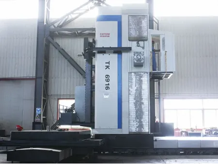

Our CNC floor type boring and milling machines are designed for complex, multi-process machining. When configured with a heavy-duty tilting CNC rotary worktable and diverse functional accessories, these machines enable continuous composite processing of milling, boring, drilling, threading, and grooving in a single setup. The core of the machine, the spindle, comprises a boring spindle (boring shaft) and a milling spindle (milling shaft), both utilizing imported SKF group bearings for superior performance. The boring shaft is meticulously crafted from 38CrMOA1A high-quality alloy steel, undergoing multiple finishing processes and surface nitriding to ensure exceptional hardness and wear resistance.
Powered by advanced SINUMERIK ONE or 828D CNC systems and AC digital servo-drive systems, these machines achieve precise multi-axis control (up to 4-axis linkage as standard) and offer functionalities like functional compensation, seamless data communication and exchange, simulation display, a variety of fixed machining cycles, and efficient tool management. Users can further enhance capabilities by opting for an automatic tool changer (ATC), various specialized milling heads, and face plates.
This machine is suitable for the machining of large-scale components in industries such as metallurgy, mining, energy and power generation (wind, thermal, nuclear), shipbuilding, steel production, and transportation equipment manufacturing.
| Models | ||||||||
| Headstock & Ram | ||||||||
| Spindle Diameter [mm] | ∅130 | ∅160 | ∅160 | ∅200 | ∅260 | ∅130 | ∅160 | ∅200 |
| Spindle Taper [ISO] | 50 | 50 | 50 | 60 | 60 | 50 | 50 | 60 |
| Spindle Speed [rpm] | 2-1500 | 2-1500 | 2-1500 | 2-1500 | 2~1500 | 2~2000 | 2~2000 | 2~1500 |
| Milling Head Diameter [mm] | ∅221.44 | ∅250 | ∅250 | ∅320 | ∅400 | ∅221.44 | ∅250 | ∅320 |
| Cross Section of Ram [mm] | 380×420 | 450×450 | 480×520 / 450×450 | 480×520 | 680×720 | 380×420 | 480×520 | 480×520 |
| Main Motor Power [kW] | 21kW to 110kW (depending on machine type) | |||||||
| Working Area | ||||||||
| Travel of Column (X-Axis) [mm] | Designed to requirements | 6000 n×1000 | Designed to requirements | Designed to requirements | Designed to requirements | 4000 N×1000 | 6000 N×1000 | 6000 N×1000 |
| Vertical Travel of Headstock (Y-Axis) [mm] | 2000-5000 | 3000-5000 | 3000-5000 | 3000-8000 | 4000-9000 | 2000-3500 | 3000-5000 | 3000-5000 |
| Travel of Spindle (W-Axis) [mm] | 700 | 1000 | 1200 | 1200 | 1700 | 700 | 1200 | 1200 |
| Travel of Ram (Z-Axis) [mm] | 800 | 1000 | 1200 | 1200-1700 | 1200-1700 | 800 | 1200 | 1200 |
| Total Travel of Spindle and Ram [mm] | 2000 | 2000 | 2400 | 2400 | 3200 | 1500 | 2400 | 2400 |
| Rotary Table Size [mm] | 2000×2500 - 5000×6000 | |||||||
| Feed Rate | ||||||||
| Travel Speed of Column (X-Axis) [mm/min] | 0.5-6000 | 0.5-6000 | 0.5-6000 | 0.5-6000 | 0.5-6000 | 0.5-10000 | 0.5-10000 | 0.5-10000 |
| Vertical Travel Speed of Headstock (Y-Axis) [mm/min] | 0.5-6000 | 0.5-6000 | 0.5-6000 | 0.5-6000 | 0.5-6000 | 0.5-10000 | 0.5-10000 | 0.5-10000 |
| Travel Speed of Spindle (W-Axis) [mm/min] | 0.5-4500 | 0.5-4500 | 0.5-4500 | 0.5-4500 | 0.5-4500 | 0.5-7500 | 0.5-7500 | 0.5-7500 |
| Travel Speed of Ram (Z-Axis) [mm/min] | 0.5-4500 | 0.5-4500 | 0.5-4500 | 0.5-4500 | 0.5-4500 | 0.5-7500 | 0.5-7500 | 0.5-7500 |
| Tool Magazine (Optional) | ||||||||
| Tool Magazine Capacity [pcs] | 40 | 40/60 | 60 | 80 | 80 | 40/60 | 40/60 | 40/60 |
| Max. Tool Weight [kg] | 25 | |||||||
| Max. Tool Diameter All pots loaded [mm] | ∅125 | |||||||
| Max. Tool Diameter Vacant adjacent pots [mm] | ∅250 | |||||||
| Max. Tool Length [mm] | 600 | |||||||
| ATC Time [sec] | 15 | |||||||
| CNC Control System (Optional) | ||||||||
| CNC Control System (Optional) | Fagor / Siemens / Fanuc | |||||||
Constructed from resin sand and wood mold castings, the machine bed’s rational structure provides a robust foundation, ensuring overall machine stability and smooth column movement. High-quality, imported ground hard-toothed racks are installed, driven by two pre-loaded gears to guarantee X-axis precision.
Made from high-quality cast iron (resin sand, wood mold casting), this sliding carriage connects to the bed via two wide guide rails (one main positioning rail, two auxiliary rails), ensuring the stability and linearity of column movement.
A double-layer frame structure of high-quality cast iron provides exceptional rigidity for headstock movement. Inlaid balance weight guide rails within the column ensure stable counterweight movement, contributing to the machine's high precision. Pre-loaded precision double-nut ball screws, driven by servo motors, manage the headstock's vertical travel along two ground guide rails.
A box-type structure cast from high-quality resin sand and wood molds, housing the main spindle components.
Ensures precise positioning at any angle. The rotary axis uses double-row cylindrical roller bearings with a central unloading device at the upper part. The rotary feed mechanism employs an AC servo motor driving a large gear ring via a backlash-eliminating reducer and double gears, automatically removing transmission gaps for high accuracy. Hydraulic floating clamping ensures reliability and stable oil film thickness during processing.
Features an operator's cabin that moves synchronously with the headstock, housing the machine control unit for convenient operation.
A hydraulic proportional valve is located at the top of the headstock housing for positioning accuracy compensation of the square ram's transverse movement; this system effectively prevents and automatically compensates for any drooping of the square ram as it extends. A pre-loaded double-nut ball screw, installed directly below the headstock body, drives the square ram.
The square ram is made of QT60-3 ductile iron material, utilizing resin sand and wood mold casting techniques. Its large cross-section effectively ensures the square ram's strength. The top of the square ram is equipped with hydraulic tie rods controlled by a proportional valve, effectively preventing the square ram from drooping and deforming when extended. Internally, the square ram is equipped with the milling spindle and the movable boring spindle (boring bar).
Features two independent hydraulic systems. A small station on the headstock's rear manages the spindle tool clamping mechanism and main drive gear shifting. A larger station, typically in the machine foundation, supplies static pressure oil, lubricating oil, and spindle cooling oil for all axes. The entire machine's hydraulic system oil is enclosed, with all oil returning to the main hydraulic station tank.
- Right Angle Milling Head
- Universal Milling Head
- Face Plate
This machine can be equipped with different tool magazines according to customer requirements. The automatic tool changer is chain-type and installed on the back of the column. Tool magazines with varying tool capacities can be equipped based on the customer's actual needs.
The tool changing operation is completed by a gripper installed on a horizontal guide rail on the column. The tool replacement cycle is automatically managed according to the workpiece's machining process requirements. To ensure safety, the tool magazine is equipped with a protective cover; if the guard door, which has an automatic safety interlock, is opened, the tool magazine immediately stops operating. An auxiliary control panel for manual tool replacement is also installed next to the tool magazine.
Rotary table units are available in various specifications and models, differing by load capacity and worktable surface dimensions. CHTEM can customize different types of rotary table units according to diverse customer needs. The worktable surface can be square, rectangular, or circular, offering a wide variety. The rotary table can be used in conjunction with floor-type boring and milling machines as well as planer-type boring and milling machines. The linear travel of a rotary table of the same size and load capacity will also vary depending on the host machine it is paired with.
We are happy to help you