Monopole Power Transmission Tower

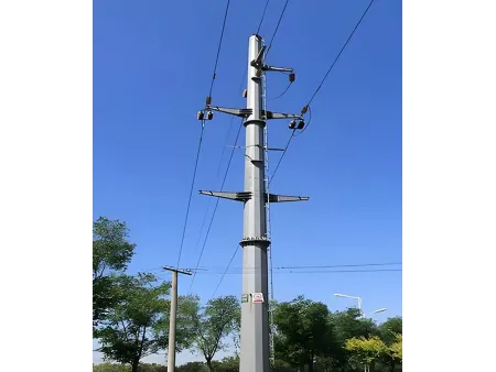

Self-supporting tower with single pole structure for power transmission lines, available in height options from 5 to 60 meters
Monopole power transmission towers use a single tubular steel pole as the main structural element. They are commonly used in urban overhead lines, substation expansions, and wind-power booster stations. Monopoles cost more than angular steel towers to produce, but their long-term maintenance expenses are reduced by about 30%.
- Design Standard ANSI/TIA-222-G/H/F; EN 1991-1-4; EN 1993-3-1
- Height Range 5–60 m, as per customer’s requirement
- Design Wind Speed 0–300 km/h, as per customer’s requirement (varies by region)
- Surface Treatment Hot-dip galvanized
- Tower Structure
The tower structure is formed from a large-diameter steel pole with a 12- to 16-sided cross-section. Using flange or overlap connections for easy transport and installation. - Space Efficiency
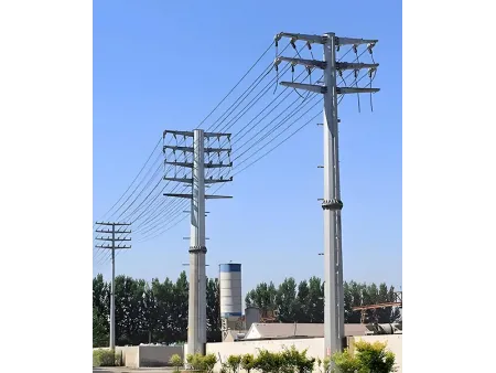
Monopoles require only one-third of the footprint of angular steel towers. They are suitable for narrow urban corridors and areas where land availability is limited. - Wind Performance
The circular profile provides a lower wind-resistance coefficient. This reduces the wind load on the tower by 40–50% in strong-wind regions, such as coastal zones. - Voltage Range
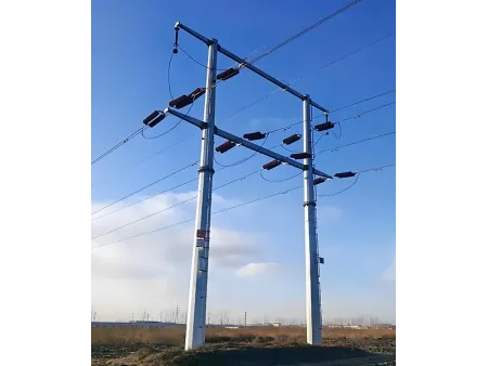
Monopole towers can support 10 kV to 220 kV transmission lines. Extra-high-voltage applications require larger diameters of 2 meters or more.
Typical Installation Environments
Monopole power transmission towers should be installed with careful consideration of soil conditions, climate, and special environmental factors to ensure long-term stability.
- Plains
Projects in plains require an evaluation of soil firmness. Soft ground should be avoided so the foundation can support both the tower body and conductor tension. - Mountain areas
Sites in mountain regions must avoid geologically weak zones. Stable areas are preferred. Temporary access roads may be needed to handle the complex terrain during construction. - Coastal regions
Coastal projects must account for salt spray, corrosion, and typhoon exposure. The foundation should include moisture-proof and corrosion-resistant measures to ensure reliable performance.
| Product | Power transmission tower |
| Tower Type | Single Circuit Tower, Double Circuit Tower, Multi Circuit Tower |
| Manufacturing Standard | DL/T 646-2012, DL/T 5214-2014, DL/T 5220-2021 |
| Quality Certification | ISO 9001: 2015; COC; Third Party Inspection Report (SGS, BV) |
| Nuts & Bolts | Grade 8.8 / 6.8 / 4.8; A325; DIN 7990, DIN 931, DIN 933; ISO 4032, ISO 4034 |
| Main Material | Q355B Plate steel |
| Height Range | 5–60 m, as per customer's requirement |
| Design Wind Speed | 0–300 km/h, as per customer's requirement (varies by region) |
| Surface Treatment | Hot-dip galvanized |
| Galvanizing Standard | ASTM A123; ISO 1461 |
| Expected Service Life | More than 20 years |
| Color Options | Silver (galvanized) or painted finish, RAL color system, customizable |
| Seismic Resistance | Up to 8° seismic intensity |
| Appropriate Temperature | −60° to 60° |
| Rated Voltage | 10 kV, 33 kV, 66 kV, 110 kV, 132 kV, 220 kV, 380 kV, 400 kV, 500 kV, 750 kV, 1000 kV |
| Certification Standard | ||
| Design Standards |
| |
| Structural Steel | ||
| Grade | Mild Steel | High Tensile Steel |
| GB/T 700 – Q235B, Q235C, Q235D | GB/T 1591 – Q355B, Q355C, Q355D, Q420B | |
| ASTM A36 | ASTM A572 Gr.50 | |
| EN 10025 – S235JR, S235J0, S235J2 | EN 10025 – S355JR, S355J0, S355J2 | |
| Design Wind Speed | Up to 300 km/h | |
| Allowable deflection | 0.5–1.0° @ operational speed | |
| Tensile strength (MPa) | 360–510 | 470–630 |
| Yield strength (t ≤ 16 mm) (MPa) | 235 | 355 / 420 |
| Elongation (%) | 20 | 24 |
| Impact strength KV (J) | 27 (20°C) - Q235B (S235JR) | 27 (20°C) - Q355B (S355JR) |
| 27 (0°C) - Q235C (S235J0) | 27 (0°C) - Q355C (S355J0) | |
| 27 (-20°C) - Q235D (S235J2) | 27 (-20°C) - Q355D (S355J2) | |
| Bolts & Nuts | ||
| Grade | Grade 4.8, 6.8, 8.8 | |
| Standards for mechanical properties | ||
| Bolts | ISO 898-1 | |
| Nuts | ISO 898-2 | |
| Washers | ISO 7089 / DIN 125 / DIN 9021 | |
| Standards for dimensions | ||
| Bolts (dimensions) | DIN 7990, DIN 931, DIN 933 | |
| Nuts (dimensions) | ISO 4032, ISO 4034 | |
| Washers (dimensions) | DIN 7989, DIN 127B, ISO 7091 | |
| Welding | ||
| Method | CO₂ Shielded Arc Welding & Submerged Arc Welding (SAW) | |
| Standard | AWS D1.1 | |
| Galvanizing | ||
| Galvanization standard of steel sections | ISO 1461 or ASTM A123/A123M | |
| Galvanization standard of bolts and nuts | ISO 1461 or ASTM A153/A153M | |
Main & Optional Components
- Anchor Bolts
- Copper Grounding Material
- Connection Plates
- Accessory Bolts
- 30-meter Transmission Tower
- 15-meter Transmission Tower
- 22-meter Transmission Tower
Laser Cutting
Laser cutting is used to shape the steel components through focused beam cutting and assisted gas removal. The process offers fast cutting speed and high dimensional accuracy (up to ±0.05 mm), while keeping heat impact to a minimum. This reduces the risk of deformation and results in clean, well-defined edges.
CNC Punching and Shearing
Steel angles are processed through CNC-controlled punching and shearing lines. Automatic feeding, positioning, punching, and cutting are all integrated into the process, keeping production running smoothly and efficiently. Precise CNC positioning keeps quality consistent, even when working with more complex parts.
Hot-Dip Galvanizing and Surface Protection
The tower is protected with hot-dip galvanizing as the main anti-corrosion treatment, along with an extra plastic coating for added protection. The zinc layer protects the steel from rust and adds strength, while the coating gives extra insulation and surface protection. This combined treatment allows the tower to maintain reliable performance for over 20 years and adapt well to harsh environments such as high and low temperatures, coastal areas, and mountainous regions.