GS Single-stage Centrifugal Blower
About GS
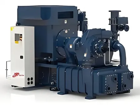
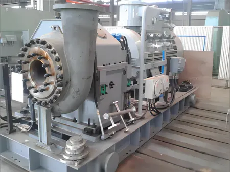
The GS single-stage centrifugal blower is dedicated for aerated wastewater treatment systems. Meanwhile, it is also capable of discharging air, nitrogen, nitrogen dioxide and other no-corrosive gases. The GS high speed centrifugal blower is characterized by wide applicability, significant energy saving, small footprint, low noise, and easy installation, operation and maintenance. The running can be controlled automatically and left unattended. Every breakdown is recorded to make convenience for the operator.
The most prominent feature of GS centrifugal blower is energy efficiency. A long term trial running of GS160 blower was started on March 1, 2009, in Qiting Sewage Treatment Plant. The plant used to use two roots blowers before. The capacity is 80m3/min and the motor power is 132kW for each. But now, the GS single-stage centrifugal blower saves 30000 RMB every month, even if it is not at full load operation.
Specifications
1. Inlet capacity: 120-400m3/min
2. Discharge pressure: 10kPa-100kPa
Main Features
1. Excellent Pneumatic Performance
The air capacity scope is 30-300m3/min and the pressure scope is 0-0.07MPa. Semi-closed, mixed-flow type 3D impellers are adopted by the centrifugal blower, and the air can flow out obliquely and gently without air vortex for less flow loss.
2. Energy Efficiency
Adjusted by inlet vane, the efficiency curve of blower unit is plain. Even under non-designed working conditions, the centrifugal blower still achieves high energy efficiency.
Parts List
1. Inlet guide vane device
The inlet guide vane is fitted in front of blower impeller. Its function is not only to enable the adjustment of blower capacity within 45% - 100%, but also to ensure the centrifugal blower to reach the highest efficiency within adjustable scope, especially when operation parameters deviate from the designed data (low temperature or low pressure).
Adjustment can be set to be automatic or manual by clicking the touch screen on blower control box. In automatic operation, the inlet guide vane is adjusted by electric operator at a set ratio after it receives 4-20mA DC signal, while under manual operation or maintenance condition, the vane is adjusted manually. The adjustment allows the centrifugal blower to meet flow requirements under actual operating conditions and achieve maximum efficiency.

2. Volute
Mature volute design grants the centrifugal blower with reliable pneumatic performance, high efficiency, and a multivariate efficiency of 85 %.
3. Step-up gear
The gear and shaft are made of heat-treated forging steel and are properly grinded. Every horizontal critical speed is within ±15% of the normal speed range, and torsion resonance speed is within ±10% of the normal speed range. All rotating parts are dynamically balanced.
The step-up gear is of parallel axis helical type with integral small gear and rotating shaft. Made of surface-quenched forging alloy steel and precisely grinded, the gear has a service index of 1.8 at least.
4. Impeller of high efficiency
The curve for the impeller is selected according to simulated working condition on computer, so it better fits for the actual flowage of gas. Meanwhile, it reduces the vane deformation caused by centrifugal force and improves the efficiency and stability.
The impeller is made of aerial aluminum alloy or stainless steel, with open path bent backward (smallest dip angle of 6 degree) and finely machined surface.
World advanced connection type is adopted for the impeller and high-speed shaft. Before delivery, over-speed and dynamic balance tests are taken to ensure the high performance of the centrifugal blower.
5. Bearing
Hydraulic radial bearing and thrust bearing are adopted. The drive shaft radial bearing is in four-flap tapered cylindrical type, while the thrust bearing is two-side load bearing with taper and tiles. The radial bearing at step-up gear shaft is tilting-pad bearings with Babbitt metal surface for ensuring rotor’s stability by enough damping. The radial bearing and thrust bearing is lubricated by pressure to supply enough lubricant film thickness under various operation conditions.
6. Automation
The use of self-tuning intelligent instrument or programmable logic control (PLC) and man-machine conversation interface for the whole running process enables the automatic/manual control of airflow.
The control system of GS series centrifugal blower includes: blower, step-up box, motor, lubricant station, inlet filter, air relief adjustable valve, shaft vibration, anti-surge system, etc. It takes digital display touch screen control panel, and can perform the full control and regulation through the corresponding software. Meanwhile, it can record various failures and analyze them intelligently as well as suggest the causes of failures.
The pivotal components for the automatic control system are imported ones to ensure the accuracy, reliability and easy maintenance of the control system.
| Art No. | Pressure | Inlet Air Capacity | Power |
| kpa | m3/min | KW | |
| | 50 | 100 | 110 |
| | 60 | 100 | 132 |
| | 70 | 100 | 160 |
| | 80 | 100 | 160 |
| | 90 | 100 | 200 |
| | 100 | 100 | 220 |
| | 50 | 120 | 132 |
| | 60 | 120 | 160 |
| | 70 | 120 | 185 |
| | 80 | 120 | 185 |
| | 90 | 120 | 200 |
| | 100 | 120 | 220 |
| | 50 | 140 | 160 |
| | 60 | 140 | 185 |
| | 70 | 140 | 200 |
| | 80 | 140 | 220 |
| | 90 | 140 | 250 |
| | 100 | 140 | 250 |
| | 50 | 160 | 185 |
| | 60 | 160 | 200 |
| | 70 | 160 | 220 |
| | 80 | 160 | 250 |
| | 90 | 160 | 280 |
| | 100 | 160 | 315 |
| | 50 | 180 | 200 |
| | 60 | 180 | 220 |
| | 70 | 180 | 250 |
| | 80 | 180 | 280 |
| | 90 | 180 | 315 |
| | 100 | 180 | 355 |
| Art No. | Pressure | Inlet Air Capacity | Power |
| kpa | m3/min | KW | |
| | 50 | 210 | 250 |
| | 60 | 210 | 280 |
| | 70 | 210 | 315 |
| | 80 | 210 | 315 |
| | 90 | 210 | 355 |
| | 100 | 210 | 400 |
| | 50 | 250 | 280 |
| | 60 | 250 | 315 |
| | 70 | 250 | 355 |
| | 80 | 250 | 400 |
| | 90 | 250 | 450 |
| | 100 | 250 | 450 |
| | 50 | 300 | 355 |
| | 60 | 300 | 400 |
| | 70 | 300 | 400 |
| | 80 | 300 | 450 |
| | 90 | 300 | 500 |
| | 100 | 300 | 560 |
| | 50 | 350 | 355 |
| | 60 | 350 | 400 |
| | 70 | 350 | 400 |
| | 80 | 350 | 450 |
| | 90 | 350 | 500 |
| | 100 | 350 | 560 |
| | 50 | 400 | 450 |
| | 60 | 400 | 500 |
| | 70 | 400 | 560 |
| | 80 | 400 | 630 |
| | 90 | 400 | 710 |
| | 100 | 400 | 800 |


