Low Voltage Power Factor Correction Capacitor
Applications
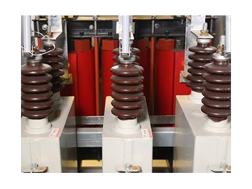
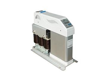
The low voltage power factor correction capacitor can be used in electrical systems to improve power factors, control the system voltage, reduce electrical loss on the wires, increase equipment output power and reduce investment costs. Our device uses self-healing metalized polypropylene film capacitors, and our miniaturization of design makes our light weight products of small size.
| Voltage range | 100V-1000V 50/60Hz |
| Rated capacity | 1-80Kvar |
| Environment temperature | -25℃/D-+55℃ |
| Maximum humidity | ≤95% |
| altitude | ≤3000(above sea level)(in some case up to5000m) |
| Shell material | Cylindrical aluminum shell, never rust |
| Over voltage | 1.1Un: 8hour,1.5Un: 30mintue,1.3Un: 1mintue |
| Over current | 1.3*IN |
| Surge current | 200 time rated current |
| Medium loss | ≤0.25W/Kvar |
| Capacitance tolerance | -5%/+5%+15%Cn(nf) |
| Test voltage end on | 2.15UN,10S |
| Test voltage on the shell | Up to UN≤660V: 3000VAC,10S; Over UN=660V: 6000V,10S |
| Cooling down method | Natural cooling |
| Working life | 100 thousand working hours.(under normal working conditions) |
| Safety characteristics | Dry technology, self-healing technique, over voltage protection device, terminal on the electric shock, over current protection |
| Discharge resistor | The discharge module has been included in the delivery(3 minutes is approaching 50V) |
| IP grade | IP20,indoor assembly(Assembly with protection, IP55, direct outdoor work) |
| Medium material | Thickening of high quality polypropylene film |
| Connecting terminal | Two stage, tangible, and protection(accord with VED106100)the maximum cable cross section area is 32mm2 |
| Standard range | IEC831-1(2),EN60831-2002,VDE0560-46,47,CE,GB/T12747-2004 |
| Installation site | Any possible position |
| Installation method | With M12 bolt |
| Temperature protection | Temperature sensor can be built in, according to the requirements of match |
| Model MJ(Y) | Rated voltage( KV) | Rated capacity (Kvar) | Total electric capacity (uF) | Rated current (A) | Installation size D*H (mm) | Shell size D*H (mm) |
| 0.25 | 5 | 254.8 | 6.7 | M16x25 | 96x240 | |
| 0.25 | 7.5 | 382.1 | 10 | M16x25 | 96x240 | |
| 0.25 | 10 | 509.5 | 10.7 | M16x25 | 96x240 | |
| 0.25 | 15 | 764.3 | 20 | M16x25 | 96x240 | |
| 0.25 | 20 | 1019 | 26.7 | M16x25 | 106x240 | |
| 0.25 | 25 | 1273.8 | 33.3 | M16x25 | 106x280 | |
| 0.25 | 30 | 1528.5 | 40 | M16x25 | 106x280 | |
| 0.45 | 10 | 157.3 | 12.8 | M12x16 | 65x240 | |
| 0.45 | 12 | 188.7 | 15.4 | M12x16 | 76x240 | |
| 0.45 | 14 | 220.2 | 18 | M12x16 | 76x240 | |
| 0.45 | 15 | 236 | 19.2 | M12x16 | 76x240 | |
| 0.45 | 16 | 251.6 | 20.5 | M12x16 | 86x240 | |
| 0.45 | 20 | 314.5 | 25.7 | M12x16 | 86x240 | |
| 0.45 | 25 | 393 | 32.1 | M16x25 | 96x240 | |
| 0.45 | 30 | 471.6 | 38.5 | M16x25 | 106x240 | |
| 0.45 | 35 | 550.2 | 44.9 | M16x25 | 116x240 | |
| 0.45 | 40 | 628.8 | 51.3 | M16x25 | 106x280 | |
| 0.45 | 45 | 707.7 | 57.7 | M16x25 | 116x280 |
Note: Please provide your working environment and technical conditions when ordering.
Ordering reminders
1. You have to select capacitors according to the network voltage. Usually the actual network voltage will be higher than the nominal network voltage. Capacitor voltage should be at least 15V higher than the nominal network voltage. For example, 380V power system should apply capacitors of at least 400V, and 660V power grids at least capacitors of 690V.
2. The maximum working temperature of the capacitor should not exceed +50 ℃. 24 hours’ average temperature should be below 40 ℃ and 30℃ in one year.
Features
1. Our low-voltage transformer features over-voltage pull-off and current breaking electrical protection.
2. Simple installation and maintenance: There is a bolt at the bottom of the device which can save user’s installation time. With the cylindrical shell our product can be installed at any angle.
3. Long lifetime: high-quality materials and media ensures our product with 100,000 hours’ lifetime.
4. Environment friendly: We use gas perfusion instead of liquid or epoxy, so there is no risk of fire or environmental pollution due to liquid leakages. We use special gases to ensure the quality of gas perfusion, in order to meet your ecological concerns.
5. Protection against electric shocks: the terminals are all cover with special sheath and is safe to touch by hands. This gives our product not only a beautiful appearance but also protection from electric shocks.
6. Self-healing features: Capacitors are able to perform self-healing under overload.
7. Over-voltage pull-off protection: At the end of capacitor service life, or when there is overload and overheating, this protects the device from explosions.
8. Terminal design: The card-type design of terminal connection parts help prevent loosening of the screws, and ensures a reliable connection.
