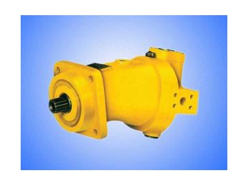
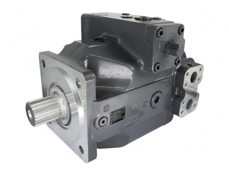
Bent Axis Piston Pump and Motor, A2F
Descriptions
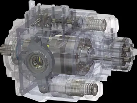
The OSA2F bent axis piston pump and motor comes with fixed displacement. It is applied to hydrostatic drive system in either open circuit or closed circuit. Working as a hydraulic pump, the flow is in direct proportion to its drive speed and displacement. While working as a hydraulic motor, its output speed is in proportion to flow and is reversely proportional to the displacement, and output torque increases as the differential pressure between high pressure side and low pressure side grows.
 Top View
 Rear Cover
Applications
The bent axis piston pump and motor is commonly founded in the hydraulic systems of metal forming machinery, cement machinery and ceramic machinery.
Features
1. The fixed displacement piston pump is provided with the rotor group in spherical valve plate design, ensuring self-centering function, combined with low peripheral speed and high efficiency.
2. Durable ball bearings and roller bearings are designed for long service life.
3. Drive shaft of the hydraulic system components can bear radial load.
4. ISO mounting flange, same with that of A6V series variable displacement motor;
5. 35MPa nominal pressure and 45-160ml/r displacement

| Size | 45 | 55 | 63 | 80 | 107 | 125 | 160 | ||||
| Displacement | Vg | mL /r | 44.3 | 54.8 | 63 | 80 | 107 | 125 | 160 | ||
| Max. speed | Closed circuit | nmax | r/min | 3750 | 3750 | 4000 | 3350 | 3000 | 3150 | 2650 | |
| Open circuit | 0.09MPa | n0.09 | r/min | 2360 | 2360 | 2550 | 2120 | 1900 | 2120 | 1650 | |
| 0.10MPa | n0.10 | r/min | 2500 | 2500 | 2700 | 2240 | 2000 | 2240 | 1750 | ||
| 0.15MPa | n0.15 | r/min | 3000 | 3000 | 3300 | 2750 | 2450 | 2750 | 2100 | ||
| Max. flow | Closed circuit | n= nmax | Qmax | L/min | 166 | 206 | 252 | 268 | 321 | 394 | 424 |
| Open circuit | n=n0.09 | Q0.09 | L/min | 122 | 125 | 156 | 164 | 197 | 257 | 256 | |
| n=n0.10 | Q0.10 | L/min | 129 | 133 | 165 | 174 | 208 | 272 | 272 | ||
| n=n0.15 | Q0.15 | L/min | 157 | 160 | 202 | 213 | 254 | 334 | 326 | ||
| Max. power | Closed circuit | Q= Qmax | Pmax | kW | 97 | 120 | 147 | 156 | 187 | 230 | 247 |
| Open circuit | Q=Q0.09 | P0.09 | kW | 71 | 75 | 93 | 99 | 119 | 154 | 154 | |
| Q=Q0.10 | P0.10 | kW | 75 | 80 | 99 | 105 | 125 | 163 | 163 | ||
| Q=Q0.15 | P0.15 | kW | 92 | 96 | 121 | 128 | 153 | 200 | 196 | ||
| Motor speed n=1450r/min Δp =35MPa | Flow | Closed circuit | QEc | L/min | 64.2 | 79.5 | 91.3 | 116 | 155 | 181 | 232 |
| Open circuit | QEo | L/min | 62.3 | 77.1 | 88.6 | 113 | 151 | 176 | 225 | ||
| Power | PE | kW | 38 | 46 | 53 | 68 | 91 | 106 | 135 | ||
| Torque | Δp =10MPa | T10 | Nm | 70.4 | 87 | 100 | 128 | 170 | 198 | 254 | |
| Δp =35MPa | Tmax | Nm | 247 | 305 | 350 | 446 | 594 | 693 | 889 | ||
| Weight | kg | 23 | 23 | 33 | 33 | 44 | 63 | 63 | |||
Operating Pressure Range (Pump)
Inlet Port Operating Pressure (Port S, A or B):
Minimum pressure: Ps min=0.08 bar
Outlet Port Operating Pressure:
Nominal Pressure: pn= 35MPa
Maximum Pressure: pmax= 40MPa
Operating Pressure Range (Motor)
Port A or B Pressure
Nominal Pressure: pn= 35MPa
Maximum Pressure: pmax= 40MPa
The sum of port A pressure and port B pressure can not exceed 70Mpa (The Max. pressure at each side is 40Mpa)
Allowable Casing Pressure
Maximum Pressure: PL max = 0.2MPa (Absolute Pressure)
Installation position is optional and the casing must be always filled with oil.
Hydraulic Fluid
Viscosity Range:
νmin = 10mm2/s Short period
νmax = 1000mm2/s Short period
Optimal operating viscosity:
νopt =16~36mm2/s
Fluid temperature range:
θmin = -25℃
θmax = 80℃
| Operating temperature range | Viscosity grade | Viscosity at 40℃ |
| ≥ 30~40℃ | VG22 | 22mm 2 /s |
| ≥ 40~50℃ | VG32 | 32mm 2 /s |
| ≥ 50~60℃ | VG46 | 46mm 2 /s |
| ≥ 60~70℃ | VG68 | 68mm 2 /s |
| ≥ 70~80℃ | VG100 | 100mm 2 /s |
Note: For filtration of hydraulic fluid, filter fineness is great to be 10μm.
| OS- | A2F | 160 | R | 2 | P | 1 |
| 1 | 2 | 3 | 4 | 5 | 6 |
| Axial piston, bent axis, fixed displacement pump/motor | A2F |
| Nominal Displacement mL /r | 45 | 55 | 63 | 80 | 107 | 125 | 160 |
| Clockwise | R |
| Counterclockwise | L |
| Double direction (Not suitable for pump in open circuit design) | W |
| ● | ● | ― | ― | ● | ― | ― | 1 | |
| ― | ● | ● | ● | ● | ● | ● | 2 |
| Keyed shaft GB1096 | P |
| Splined shaft DIN5480 | Z |
| Splined shaft GB3478.1 | S |
| Port A and B, on two sides of rear cover, threaded | ● | ● | ● | ● | ● | ● | ● | 1 |
| Port A and B, on two sides of rear cover, flange | ● | ● | ● | ● | ● | ● | ● | 2 |
| Port B on the side of rear cover, SAE flange; Port S on rear side, flange | ● | ● | ● | ● | ● | ● | ● | 3 |
●=available,○=In preparation,―=without

| Size | α° | A1 | A2 | A3 | A4 | A5 | A6 | φA7 | A8 | A9 | A10 | φA11 | φA12 | A13 |
| 45 | 20 | 384 | 20 | - | 77 | - | 63 | 125 | 10 | M12 | 28 | 160 | 16 | 150 |
| 55 | 25 | 381 | 20 | 108 | 77 | 32 | 63 | 125 | 10 | M12 | 28 | 160 | 16 | 150 |
| 63 | 20 | 452 | 23 | 137 | - | 32 | - | 140 | 10 | M12 | 28 | 180 | 16 | 165 |
| 80 | 25 | 450 | 23 | 137 | - | 32 | - | 140 | 10 | M12 | 28 | 180 | 16 | 165 |
| 107 | 25 | 476 | 25 | 130 | 90 | 40 | 80 | 160 | 12 | M12 | 28 | 200 | 20 | 190 |
| 125 | 20 | 552 | 28 | 156 | - | 40 | - | 180 | 10 | M16 | 36 | 224 | 20 | 210 |
| 160 | 25 | 547 | 28 | 156 | - | 40 | - | 180 | 10 | M16 | 36 | 224 | 20 | 210 |
| Size | φA14 | A15 | A16 | A17 | A18 | A19 | A20 | A21 | A22 | A23 |
| 45 | 30 | 60 | 8 | W30 × 2 × 14 × 9g | 35 | EXT14Z × 2m × 30R × 5f | 35 | 31.5 | 150 | 183 |
| 55 | 30 | 60 | 8 | W30 × 2 × 14 × 9g | 35 | EXT14Z × 2m × 30R × 5f | 35 | 31.5 | 150 | 183 |
| 63 | 35 | 70 | 10 | W35 × 2 × 16 × 9g | 40 | EXT16Z × 2m × 30R × 5f | 40 | 36 | 173 | 213 |
| 80 | 35 | 70 | 10 | W35 × 2 × 16 × 9g | 40 | EXT16Z × 2m × 30R × 5f | 40 | 36 | 173 | 213 |
| 107 | 40 | 80 | 12 | W40 × 2 × 18 × 9g | 45 | EXT18Z × 2m × 30R × 5f | 45 | 40 | 190 | 230 |
| 125 | 45 | 90 | 14 | W45 × 2 × 21 × 9g | 50 | EXT21Z × 2m × 30R × 5f | 50 | 45 | 212 | 262 |
| 160 | 45 | 90 | 14 | W45 × 2 × 21 × 9g | 50 | EXT21Z × 2m × 30R × 5f | 50 | 45 | 212 | 262 |

| Size | B1 | B2 | B3 | B4 | B5 | B6 | B7 | B8 | B9 | B10 | B11 |
| 45 | 132 | M33 × 2 depth 18 | 126 | φ19 | 50.8 | 23.8 | 4-M10 depth 16 | 63 | φ19 | 50.8 | 23.8 |
| 55 | 132 | M33 × 2 depth 18 | 126 | φ19 | 50.8 | 23.8 | 4-M10 depth 16 | 63 | φ19 | 50.8 | 23.8 |
| 63 | 156 | M42 × 2 depth 20 | 150 | φ25 | 57.2 | 27.8 | 4-M12 depth 16 | 75 | φ25 | 57.2 | 27.8 |
| 80 | 156 | M42 × 2 depth 20 | 150 | φ25 | 57.2 | 27.8 | 4-M12 depth 16 | 75 | φ25 | 57.2 | 27.8 |
| 107 | 165 | M42 × 2 depth 20 | 160 | φ25 | 57.2 | 27.8 | 4-M12 depth 18 | 80 | φ25 | 57.2 | 27.8 |
| 125 | 195 | M48 × 2 depth 22 | 190 | φ32 | 66.7 | 31.8 | 4-M14 depth 21 | 95 | φ32 | 66.7 | 31.8 |
| 160 | 195 | M48 × 2 depth 22 | 190 | φ32 | 66.7 | 31.8 | 4-M14 depth 21 | 95 | φ32 | 66.7 | 31.8 |
| Size | B12 | B13 | B14 | B15 | B16 | B17 | Oil drain port T |
| 45 | 4-M10 depth 16 | 29 | φ42 | 48 | 48 | 4-M10 depth 16 | M18 × 1.5 |
| 55 | 4-M10 depth 16 | 29 | φ42 | 48 | 48 | 4-M10 depth 16 | M18 × 1.5 |
| 63 | 4-M12 depth 16 | 35.5 | φ53 | 60 | 60 | 4-M12 depth 18 | M18 × 1.5 |
| 80 | 4-M12 depth 16 | 35.5 | φ53 | 60 | 60 | 4-M12 depth 18 | M18 × 1.5 |
| 107 | 4-M12 depth 18 | 35.5 | φ53 | 60 | 60 | 4-M12 depth 18 | M18 × 1.5 |
| 125 | 4-M14 depth 21 | 42.2 | φ68 | 75 | 75 | 4-M16 depth 24 | M22 × 1.5 |
| 160 | 4-M14 depth 21 | 42.2 | φ68 | 75 | 75 | 4-M16 depth 24 | M22 × 1.5 |


