Axial Piston Pump, A4V
Overview
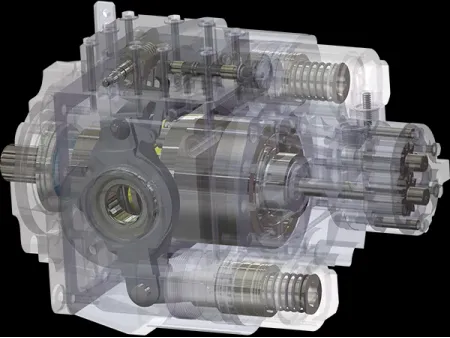
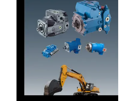
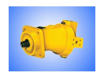
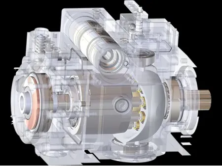
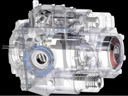
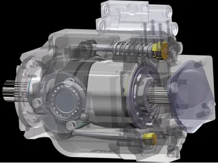
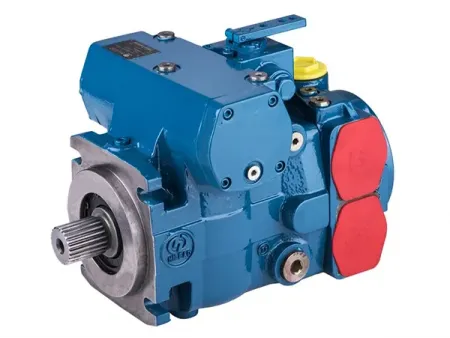
This hydraulic pump of OSA4VSO model is a variable displacement axial piston pump in swashplate design. It is built for the hydraulic drive system with open circuit. With a through-shaft construction, its rated operating pressure is up to 35MPa.The swashplate pump comes with state of the art modular design that ensures high flexibility in use. A swivel angle indicator for the swashplate is designed for easy operation.
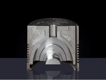
Depending on the valve plate of spherical design, the reciprocating pump boasts a self-alignment property. Due to a design that there is a 5° inclined angle between the piston axis and the cylinder block axis, pump's rotational speed can be improved. The axial piston pump delivers a self-reliant circulating washing function that can improve the working condition of bearings. Full arrangement of cylindrical roller bearings makes the bearing capacity dramatically enhanced.
Applications
The axial piston pump is mainly applied to the hydraulic system of metallurgical machinery, ceramic machinery and metal forming machinery.

- Variable Displacement Mechanism
- Control Valve
- Shaft End
Features
1. The hydraulic piston pump's capacity is in direct proportion to its rotational speed and displacement. Stepless displacement adjustment can be done by adjusting the swivel angle of swash plate.
2. In virtue of a through-shaft construction, it can be connected to other pump to form a combination pump.
3. Position constraint return mechanism;
4. Valve plate comes in spherical design. Pistons are arranged around the shaft with their axes inclined to shaft axis.
5. The axial piston pump is equipped with an indicator for the swivel angle of swashplate;
6. Stepless variable displacement;
7. Excellent suction performance;
8. Up to 35Mpa rated operating pressure;
9. Fast response;
10. Low noise;
11. Long service life;
12. Superior power to weight ratio;
13. Modular design;
14. Drive shaft of the hydraulic unit can bear axial and radial load.
15. Installation position is optional.
15. It is able to run on HF fluid, with operating parameter lowered.
Check the PDF file attachment for parameter list, characteristic curves, through drives, dimensions, installation methods and other information.
1. Operating Pressure Range-Inlet Side
Pressure of suction port S (Absolute pressure)
Minimum pressure: Ps min=0.8 bar
Maximum pressure: Ps max=30 bar
Notes:
1) To avoid being damaged, the axial piston pump has to keep a minimum pressure at the suction port S. The minimum inlet pressure depends on pump's rotational speed and displacement.
2) Inlet pressure is static input pressure or the minimum dynamic value of boost pressure.

2. Operating Pressure Range-Outlet Side
Pressure of port B (Absolute pressure)
Nominal pressure: Pn=350 bar
Peak pressure: Pmax=400 bar
3. Flow Direction
S→B
4. Casing Oil Drain Pressure
Maximum allowable pressure of the drain port (absolute pressure) depends on the rotational speed of the pump;
Maximum casing drain pressure (absolute pressure): P L max =4 bar

| No. | Model | Specifications |
| 1 | OS4V | OS4V (S) O 40 DR(DRG)/10R (L) -PPB13NOO |
| 2 | OS4V (S) O 71 DR(DRG)/10R (L) -PPB13NOO | |
| 3 | OS4V (S) O 125 DR(DRG)/30R (L) -PPB13NOO | |
| 4 | OS4V (S) O 180 DR(DRG)/30R (L) -PPB13NOO | |
| 5 | OS4V (S) O 250 DR(DRG)/30R (L) -PPB13NOO |
| No. | Model | Specifications |
| 1 | OS4V | OS4V (S) O 125 LR(LRG)/30R (L) -PPB13NOO |
| 2 | OS4V (S) O 180 LR(LRG)/30R (L) -PPB13NOO | |
| 3 | OS4V (S) O 250 LR(LRG)/30R (L) -PPB13NOO |
| E | OS4VS | O | 125 | DR | / | 30 | R | --- | P | P | B | 13 | U | 34 |
| 1 | 2 | 3 | 4 | 5 | 6 | 7 | 8 | 9 | 10 | 11 | 12 | 13 |
| Mineral oil (No Code) | - |
| HFA , HFB , HFC Hydraulic fluid | E |
| Axial piston, straight shaft, variable | OS4VS |
| Open circuit | O |
| Nominal displacement mL/r | 40 | 71 | 125 | 180 | 250 | 355 |
| Pressure control DR | ● | ● | ● | ● | ● | 〇 | DR |
| Pressure control for parallel operation DP | ● | ● | ● | ● | ● | 〇 | DP |
| Flow control FR | ● | ● | ● | ● | ● | 〇 | FR |
| Pressure and flow control DFR | ● | ● | ● | ● | ● | 〇 | DFR |
| Power control LR2 | ● | ● | ● | ● | ● | 〇 | LR2 |
| Remote power control LR3 | ● | ● | ● | ● | ● | 〇 | LR3 |
| Manual control MA | ● | ● | ● | ● | ● | 〇 | MA |
| Motor control EM | 〇 | 〇 | 〇 | 〇 | 〇 | 〇 | EM |
| Electronic control E 〇 | 〇 | 〇 | 〇 | 〇 | 〇 | 〇 | E 〇 |
| ● | ● | - | - | - | - | 10 | |
| - | - | ● | ● | ● | 〇 | 30 |
| Clockwise | R |
| Counterclockwise | L |
| NBR , Shaft seal FKM | P |
| FKM | V |
| Keyed shaft DIN6885 | P |
| Splined shaft DIN5480 | Z |
10. Mounting Flange
ISO 4 Holes
| Suction port S , Pressure port B , Auxiliary port B1 | 13 |
| Suction port S, Pressure port B , the second pressure port B1 | 25 |
| 40 | 71 | 125 | 180 | 250 | 355 | ||||
| Without through drive | ● | ● | ● | ● | ● | 〇 | N00 | ||
| With through drive, mounting dimensions of subordinate pump are as follows | ● | ● | - | - | - | - | K | ||
| Universal through drive, mounting dimensions of subordinate pump are as follows | - | - | ● | ● | ● | 〇 | U | ||
| Flange | Splined shaft | Acceptable subordinate pump | |||||||
| ISO 125 , 4 Holes | W3 2 ×2×30×14×9g | OS4VSO40 | ● | ● | ● | ● | ● | 〇 | 31 |
| ISO 140 , 4 Holes | W40×2×30×18×9g | OS4VSO 71 | - | • | • | • | • | 〇 | 33 |
| IISO 160 , 4 Holes | W50×2×30×24×9g | OS4VSO 125 | - | - | • | • | • | 〇 | 34 |
| ISO 160 , 4 Holes | W50×2×30×24×9g | OS4VSO 180 | - | - | - | • | • | 〇 | 34 |
| ISO 224 , 4 Holes | W60× 2 × 30 ×28 ×9g | OS4VSO 250 | - | - | - | - | • | 〇 | 35 |
| ISO 224 , 4 Holes | W70×3×30×22×9g | OS4VSO 355 | - | - | - | - | - | 〇 | 77 |
| ISO 80 , 2 Holes | 3/4in11T16/32DP S shaft | OS10VSO18 | • | • | 〇 | 〇 | 〇 | 〇 | B2 |
| ISO 100 , 2 Holes | 7/8in13T16/32DP S shaft | OS10VSO 28 | ● | ● | ● | ● | ● | 〇 | B3 |
| ISO 100 , 2 Holes | 1in 15T16/32DP S shaft | OS10VSO 45 | ● | ● | ● | ● | ● | 〇 | B4 |
| ISO 125 , 2 Holes | 1 1/4in14T12/24DPS shaft | OS10VSO 71/31 | - | • | • | • | • | 〇 | B5 |
| ISO 125 , 2 Holes | 1 1/2in17T12/24DPS shaft | OS10VSO 100/31 | - | - | • | • | • | 〇 | B6 |
| ISO 180 , 4 Holes | 1 3/4in13T8/16DP S shaft | OS10VSO 140 | - | - | - | • | • | 〇 | B7 |
| ISO 160 , 4 Holes | 1 1/4in14T12/24DPS shaft | OS10VSO 71/32 | - | 〇 | 〇 | 〇 | 〇 | 〇 | B8 |
| ISO 180 , 4 Holes | 1 1/2in17T12/24DPS shaft | OS10VSO 100/32 | - | - | 〇 | 〇 | 〇 | o | B9 |
| SAE82 , 2 Holes | 3/4in11T16/32DP S shaft | OS10VSO 18 | • | • | 〇 | 〇 | 〇 | 〇 | 52 |
| SAE101, 2 Holes | 7/8in13T16/32DP S shaft | OS10VO 28 | ● | ● | ● | ● | ● | 〇 | 68 |
| SAC 101, 2 Holes | 1 in 15T 16/32DP S shaft | OS10VO 45 | ● | ● | ● | ● | ● | 〇 | 04 |
| SAE127, 2 Holes | 1 1/4in14T12/24DPS shaft | OS10VO 71 | - | • | • | • | • | o | 07 |
| SAE127, 2 Holes | 1 1/2in17T12/24DPS shaft | OS10VO 100 | - | - | • | • | • | 〇 | 24 |
| SAE152, 4 Holes | 1 3/4in13T8/16DP S shaft | OS10VO 140 | - | - | - | • | • | 〇 | 17 |
| Shaft end of the pump with through drive comes with no couplings. It is enclosed with blind flange. | ● | ● | ● | ● | ● | 〇 | 99 | ||
Description of combination pump: Two pumps can be connected in series by their head and end, namely integrated to be a combination pump by the means of through-shaft, and the second pump of the series combination is called the subordinate pump.
If placing an order, please notice that the model of the combination pump is a combination of the first pump model and the second pump model. Example: OS4VSO125DR/30R-PPB13U34 OS4VSO125DR/30R-PPB13N00


