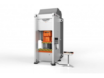
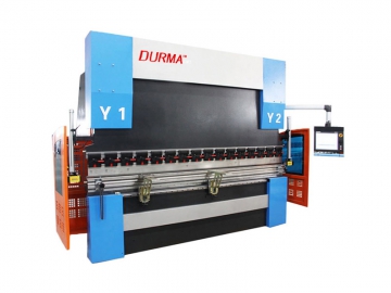
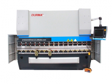
Servo Drive CNC Hydraulic Press
- Work mode selection: There are two work regulations: adjustment and semi-automatic (single cycle). There are two forming methods: constant pressure forming and fixed forming.
- The slider is equipped with a displacement sensor sending device and a travel limit limiting device, designed to effectively prevent over traveling.
- The hydraulic electrical and electronic control system is equipped with a liquid crystal touch screen, which can works with pressure and displacement sensors to achieve digital display of the slider speed, position and pressure.
- Oil blocking measures are set on the joints of the upper beam, the slider and the cylinder of the servo drive CNC hydraulic press.
- Hydraulic system low-pressure and large-diameter pipelines are equipped with flexible joints to offer a better vibration resistance. Pipes with a diameter of more than 32 are all flanged to ensure an excellent shock and leak resistance.
| Type | YL34K-100 | YL34K-160 | YL34K-200 | YL34K-250 | YL34K-315 | YL34K-400 | YL34K-500 | YL34K-630 | ||
| Nominal force | kN | 630+200×2 | 1000+300×2 | 1000+500×2 | 1250+630×2 | 1600+800×2 | 2000+1000×2 | 2500+1250×2 | 3150+1600×2 | |
| Return force | kN | 37×2 | 60×2 | 60×2 | 69×2 | 76×2 | 165×2 | 277×2 | 408×2 | |
| Slide stroke | mm | 600 | 600 | 700 | 700 | 800 | 800 | 1000 | 1200 | |
| Max. shut height | mm | 750 | 750 | 1000 | 1000 | 1200 | 1200 | 1400 | 1600 | |
| Nominal force of hydraulic die cushion | kN | 400 | 630 | 800 | 800 | 1250 | 1250 | 1000×2 | 1000×2 | |
| Return force of hydraulic die cushion | kN | 147 | 250 | 280 | 280 | 360 | 360 | 320×2 | 320×2 | |
| Stroke of hydraulic die cushion | mm | 200 | 200 | 250 | 250 | 300 | 300 | 350 | 400 | |
| Slide speed | Idle stroke | mm/s | 400 | 380 | 300 | 450 | 500 | 400 | 500 | 500 |
| Pressing | mm/s | 29 | 23 | 18 | 24 | 24 | 25 | 25 | 25 | |
| Return | mm/s | 400 | 300 | 300 | 430 | 500 | 300 | 225 | 190 | |
| Ejecting speed | Eject | mm | 72 | 58 | 45 | 75 | 60 | 75 | 62 | 78 |
| Return | mm | 200 | 120 | 130 | 210 | 200 | 560 | 190 | 240 | |
| Bolster size | LR | mm | 1000 | 1250 | 1200 | 1200 | 1500 | 2000 | 3000 | 3500 |
| FB | mm | 800 | 900 | 1000 | 1000 | 1200 | 1500 | 2000 | 2000 | |
| Hydraulic die cushion size | LR | mm | 650 | 970 | 950 | 950 | 1120 | 1420 | 2320 | 2920 |
| FB | mm | 650 | 670 | 800 | 800 | 820 | 1120 | 1420 | 1420 | |
| Machine outline size | LR | mm | 2880 | 2300 | 3280 | 3380 | 3900 | 4500 | 5600 | 6200 |
| FB | mm | 1650 | 1600 | 2000 | 2100 | 2500 | 3000 | 3500 | 3600 | |
| Above floor | mm | 3250 | 4300 | 3900 | 4300 | 5200 | 5600 | 6200 | 7200 | |
| Main motor power | kW | 30 | 37 | 37 | 55 | 75 | 90 | 110 | 132 | |
| Machine weight | kg | 7500 | 13500 | 14500 | 17500 | 26500 | 42000 | 88000 | 120000 | |
Main Structure Description
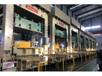
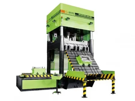
The servo drive CNC hydraulic press has incorporated all the best features of CNC hydraulic presses from big names around the world, and has imported the most advanced technology for the structural design. The entire machine has been optimized through the computer's finite element design, which focuses on overall performance of the hydraulic press. This press is durable, stiff and reliable thanks to its unique product design style.
- The body of the hydraulic press is an integral frame structure that is both stiff and strong.
- The machine body is an integral welded component, with carbon dioxide gas shielded welding used for welding to ensure the welding quality. After welding, the annealing treatment is done using a fireplace in order to fully eliminate any welding distortion and stress to ensure the welding component accuracy.
- The machine body uses a floor boring and milling machine for processing. It can complete machining of important surfaces such as the body, worktable, guide rail surface and cylinder mounting hole all in a single clamping, thus improving overall machine tool accuracy.
Slider
The slider is a full steel plate welded box structure, using carbon dioxide gas shielded welding, and after the welding, annealing in the fireplace, roughing and re-vibration aging treatment to eliminate residual stress, the slider goes through a pentahedral machining center and CNC floor to ceiling milling machine processing, so that the processing finish, shape and position tolerances, and dimensional accuracy are extremely high. The slider uses a single-cylinder, double-cylinder or multi-cylinder drive according to the worktable size, with the cylinder structure featuring a combination of a piston cylinder, a plunger cylinder or a piston cylinder and a plunger cylinder according to actual working conditions. A square-shaped all-steel rail is arranged on the four corners of the left and right columns and shaped in a four corner, 8 plane designed for guiding the slider. The slider rails can be independently adjusted in the front, rear, left and right directions, which ensures the accuracy is not easily deviated from, gives the equipment a high guidance accuracy and a strong resistance to a partial load capacity. The slider is equipped with a displacement center, which is capable of the stroke and position digital display, in addition to limiting the position from going beyond what was set by the displacement center, as well as limited the stroke control switch to ensure it does not exceed limits.
Hydraulic cylinder
All cylinders, piston rods, and plunger rods are made using high-quality materials and are manufactured using hydraulic cylinders. All piston rod surfaces of the main fuel tank are subjected to a strict heat treatment. The hardness of the guide section is about HRC45. The piston rods of all the bottom cylinders are quenched and tempered, and the surface is plated with hard chrome. The chrome plating depth is 0.05 mm. The main seal of the cylinder uses a new YX-type seal ring with a low friction resistance and high pressure resistance. The seal ring is made using German imported raw materials (the main seal can also be used to separate the ring and seal according to design requirements or user requirements). The non-metallic wear ring is used to guide the movement of the piston rod, avoiding the cylinder pulling phenomenon that may be caused by metal contact.
Description of the hydraulic system
The hydraulic control system of the machine is composed of a pump station, a filling valve and a pipeline. The pump station contains an oil pump motor unit, a hydraulic integrated control valve and a fuel tank. The pump station is installed above the host.
Oil pump motor unit
The pump motor group is connected by the EMB servo motor internal gear pump through the mounting seat and the coupling section, and provides the power source to the host through the hydraulic circuit. The power source features a number of attractive features:
- Energy saving
- Noise is significantly reduced
- Reduce reactive power consumption and reduce the temperature rise of the hydraulic system
- Repeated positioning accuracy is high
- The efficiency of machine tools has been significantly improved
- The machine speed is adjustable
The above characteristics are particularly suitable for hydraulic press work.
Hydraulic integrated control valve
The hydraulic integrated control valve uses a domestic two-way cartridge valve centralized control. The two-way cartridge valve and the first conductive magnetic valve are both sourced from Rexroth, and the installation size meets international standards, so that same specification components are completely interchangeable. The hydraulic valve integrated system carries out pressure regulation, commutation, pressure maintenance, unloading, support, speed conversion, and overpressure protection. The lower control block of the master cylinder is equipped with a non-slip block falling device and a safety valve. When the slider is stopped at any position, the device will automatically close to ensure the reliability and safety of the slider. When a valve accident occurs in the lower chamber when the card is deadlocked, the bypass safety valve immediately acts as an oil drain to avoid safety accidents, and the double safety circuit makes the possibility of cylinder upset almost zero.
Fuel tank
The fuel tank is a welded steel plate with a closed structure. It is divided into an oil suction area and a return oil area, separated by a filter screen, and a window hole is opened in the wall to clean the oil tank and replace the filter screen. A liquid temperature thermometer is installed on the tank to observe the oil level and measure the oil temperature.
Filling valve
The filling valve uses a large-diameter professionally manufactured filling valve to meet the process requirements of the rapid down and rapid return of the hydraulic press, which greatly improves the working efficiency. The filling valve is installed on the top of the main oil tank, and when the slider descends quickly due to its own weight, the pump will operate. Oil cannot be supplied to the upper chamber of the master cylinder in time, and the main valve of the master cylinder forms a negative pressure suction main valve of the filling valve, so that a large amount of oil in the fuel tank flows into the master cylinder, in order to meet slider speed requirements. When the slide returns, the control fluid is topped off by a small pre-discharge valve, so that the main cylinder is depressurized, and then the main valve of the liquid filling valve is opened, facilitating oil drainage back into the charging tank from the main cylinder.
Pipeline
The pipeline is a combination of a rigid pipe and a hose. The rigid pipe is a high-pressure seamless welding tubing. The hose is a steel wire braided or steel wire coiled structure. The standard connector is used within 20 bores, and the flange diameter is used above 20 ports. All hard tubes are pickled, passivated and corrosion treated before welding to ensure that the hydraulic lines remain clean. The piping layout is neat and beautiful, easy to overhaul, and attached using anti-vibration pipe clamps.
