4 Roll Plate Bending Machine
Hydraulic bending roll for bending metal sheets and plates into curved, round and conical shapes
Hydraulic bending roll for bending metal sheets and plates into curved, round and conical shapes
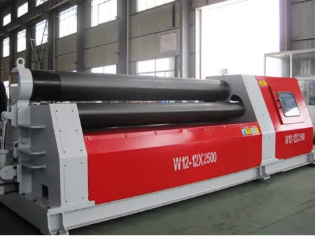
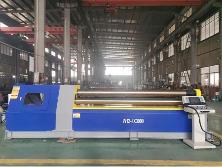
This 4-roll plate bending machine is a highly specialized device engineered for metal sheet bending and correction. It is specifically designed to handle the forming and bending of metal sheets, with the capability to pre-bend the ends of the sheet in a single pass, roll cylindrical and curved workpieces, and perform initial rough shaping of the metal sheets.
- Features
- Specifications
- Components
- The top roller is the primary driving roller, while the bottom and side rollers are driven rollers, rotating via the friction force between the steel plate and the rollers.
- The top roller's position is fixed, allowing only rotational movements. Lifting displacement is not performed. The flipping and resetting of the bearing body on the front side of the top roller are controlled by a cylinder.
- Both the bottom roller and the side roller are adjustable via oil cylinders at their respective ends, facilitating vertical movements.
- The left and right frames form the core of the machine, featuring a welded structure mounted on a base of integral welding. All operational controls are centralized on the operating table.
The 4-roll plate bending machine is extensively used in various industrial applications including shipbuilding for metal hull bending, forming boiler wall equipment in energy sectors, shaping components in aviation machinery, bending bridge steel structures, and general metal bending in machinery manufacturing. This versatility makes it an essential asset in heavy-duty metal fabrication tasks.
- Wind Turbines
- Rocket Shells
- Oil Tanks
- Ship Hulls
| Model | Max. bending thickness (mm) | Pre-bending thickness (mm) | Max. working length of roller (mm) | Top roller diameter (mm) | Bottom roller diameter (mm) | Side roller diameter (mm) | Main motor (kW) |
| 4 | 3.5 | 2050 | 160 | 140 | 120 | 3 | |
| 6 | 5 | 2050 | 190 | 170 | 150 | 4 | |
| 8 | 6.5 | 2050 | 210 | 190 | 170 | 5.5 | |
| 10 | 8 | 2050 | 230 | 210 | 190 | 7.5 | |
| 12 | 10 | 2050 | 270 | 250 | 210 | 11 | |
| 16 | 13 | 2050 | 300 | 270 | 220 | 11 | |
| 20 | 16 | 2050 | 330 | 300 | 240 | 11 | |
| 25 | 20 | 2050 | 360 | 330 | 250 | 15 | |
| 30 | 25 | 2050 | 390 | 360 | 300 | 18.5 | |
| 35 | 28 | 2050 | 430 | 390 | 330 | 22 | |
| 40 | 32 | 2050 | 460 | 420 | 360 | 30 | |
| 4 | 3.5 | 2550 | 190 | 170 | 150 | 4 | |
| 6 | 5 | 2550 | 210 | 190 | 170 | 5.5 | |
| 8 | 6.5 | 2550 | 230 | 210 | 190 | 7.5 | |
| 10 | 8 | 2550 | 270 | 250 | 210 | 11 | |
| 12 | 10 | 2550 | 300 | 270 | 220 | 11 | |
| 16 | 13 | 2550 | 330 | 300 | 240 | 11 | |
| 20 | 16 | 2550 | 360 | 330 | 250 | 15 | |
| 25 | 20 | 2550 | 390 | 360 | 300 | 18.5 | |
| 30 | 25 | 2550 | 430 | 390 | 330 | 22 | |
| 35 | 28 | 2550 | 460 | 420 | 360 | 30 | |
| 40 | 32 | 2550 | 510 | 460 | 390 | 37 | |
| 4 | 3.5 | 3100 | 210 | 190 | 170 | 5.5 | |
| 6 | 5 | 3100 | 230 | 210 | 190 | 7.5 | |
| 8 | 6.5 | 3100 | 270 | 250 | 210 | 11 | |
| 10 | 8 | 3100 | 300 | 270 | 220 | 11 | |
| 12 | 10 | 3100 | 330 | 300 | 240 | 11 | |
| 16 | 13 | 3100 | 360 | 330 | 250 | 15 | |
| 20 | 16 | 3100 | 390 | 360 | 300 | 18.5 | |
| 25 | 20 | 3100 | 430 | 390 | 330 | 22 | |
| 30 | 25 | 3100 | 460 | 420 | 360 | 30 | |
| 35 | 28 | 3100 | 510 | 460 | 390 | 37 | |
| 40 | 32 | 3100 | 550 | 510 | 420 | 45 |
Main Drive Mechanism
The primary driving mechanism is the upper roller, powered by a hydraulic motor connected through a reduction gearbox to ensure a consistent rolling speed of approximately 4 meters per minute, facilitating efficient steel plate feeding.
Roller Mechanics
Hydraulic systems enable both simultaneous and independent lifting of the lower roller and side rollers. The system also manages the dumping and resetting of the inverted head.
Hydraulic System
Features an independent hydraulic pump station comprised of an oil pump motor, hydraulic valve group, and auxiliary piping.
- The hydraulic pump is equipped with an oil filter to ensure clean oil supply.
- The system is designed to be leak-resistant and easy to maintain, using high-quality seals and components from renowned manufacturers.
- The synchronization of roller lifting is managed by a PLC system, ensuring high precision through sensors and hydraulic valves (including electromagnetic reversing valve, throttle valve, and hydraulic control check valve).
Electronic Control System
- Comprises an electric control cabinet, an operational console, and a handheld control box.
- The PLC and other control devices are housed in a distribution cabinet, with a touch screen interface for operational ease.
- Components primarily sourced from Schneider Electric, with the main electrical system designed for three-phase 380V/50Hz AC. Includes comprehensive motor protection against short circuits and overheating.


