Flow Totalizer, HG56
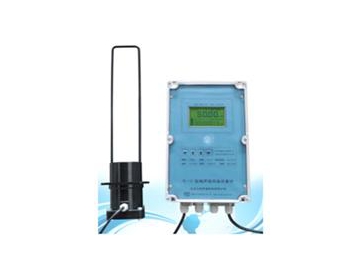
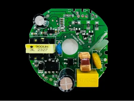
HGFT-5600 series flow totalizer is produced by automatic chip mounters based on surface mounting technology. It offers high anti-jamming performance. In addition to flow totalizing, it can also serve as a flow measurement and control solution for liquids, general gases, superheated steam, saturated steam, etc. It supports collection, display, control, remote transmission, communication, and printing of on-site signals such as temperature, pressure, and flow. These functions make flow totalizers a reliable digital collection and control system.
Functions of the Flow Totalizer
1. Automatic calculation and cumulation of mass flow
2. Automatic calculation and cumulation of standard volumetric flow
3. Simultaneous display of measured values of instantaneous flow and cumulative flow (unit of total flow may be set without limitation)
4. Switch between display of measured value of instantaneous flow, time, current cumulative flow, total cumulative flow of 11-digit, flow (differential pressure, frequency) input, pressure compensation input value, temperature compensation input value;
5. The flow totalizer has small signals cut-off function (display “0”when instantaneous flow is less than set value)
6. Quantitative control of flow available
7. Automatic temperature and pressure compensation available
8. The following sensors may be chosen through programming:
(1) △P: differential pressure type flow sensor input
(2) △P, T: differential pressure type flow sensor and temperature sensor input
(3) △P, P, T: differential pressure type flow sensor, pressure sensor and temperature sensor input
(4) f: frequency type flow sensor input
(5) f, T: frequency type flow sensor and temperature sensor input
(6) f, P: frequency type flow sensor and temperature sensor input
(7) f, P, T: frequency type flow sensor, pressure sensor and temperature sensor input
(8) G: flow sensor (linear flow signals) input
(9) G, T: flow sensor and temperature sensor input
(10) G, P: flow sensor and pressure sensor input
(11) G, T, P: flow sensor, temperature sensor and pressure sensor input
9. The flow totalizer offers three kinds of compensation
(1) Automatic temperature compensation
(2) Automatic pressure compensation
(3) Automatic temperature and pressure compensation
Display Functions of the Flow Totalizer
1. Display of measured value of instantaneous flow, current cumulative flow, differential pressure, pressure compensation, temperature compensation and frequency of each channel;
2. PV SV display of cumulative flow: 11 digits (0 ~ 99999999.999)
3. Display of current date and time
4. Storage of total cumulative flow under power failure; automatic clear of total cumulative flow when it reaches full range (99999999.999); current cumulative flow will not be stored under power failure.
| Input | |||||
| Input signals | Current | Voltage | Resistance | Thermocouple | |
| Input Impedance | ≤250Ω | ≥500KΩ | |||
| Maximum input current | 30mA | ||||
| Maximum input voltage | <6V | ||||
| Output | |||||
| Output signals | Current | Voltage | Relay | 24V (distribution or feed) | |
| Output load capability | ≤500Ω | ≥250 KΩ (Note: Please replace the module if higher load capacity is required) | AC220V/2A(large) DC24V/2A(large) | ≤30mA | |
| Comprehensive parameter | |||||
| Accuracy | 0.2%FS | ||||
| Setting Mode | Light touch control panel for digital setting, the value of which will be stored permanently even in case of power failure; set value locked and protected with password | ||||
| Display mode | Measured value of instantaneous flow: 0 ~ 99999 Measured value of cumulative flow: 0 ~ 99999999.999 Measured value of temperature compensation: -1999 ~ 9999 Measured value of pressure compensation: -1999 ~ 9999 Measured value of flow (differential pressure, frequency): -1999 ~ 9999 Current time and LED working status displayed | ||||
| Operating environment | Ambient temperature: 0 ~50 ℃ ; relative humidity: ≤ 85%; far from strong corrosive gas | ||||
| Power supply | AC 100 ~ 240V (switch power), (50-60HZ); DC 20 ~ 29V (switch power) | ||||
| Power consumption | ≤6W | ||||
| Structure | Standard snap-in structure | ||||
| Communication | Standard MODBUS communication protocol, communication distance of RS-485 up to1 km, and communication distance of RS-232 up to 15 meters. Note: active converter is preferred if the instrument has communication function. | ||||


