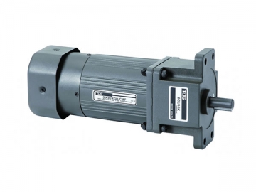
1. The micro AC speed-adjusting gear motor features a controller and motor unit that does not require extra wiring because they only need to be connected one time. Speed of the motor can be simply controlled by the external potentiometer. The speed control circuit and capacitor are mounted on the controller.
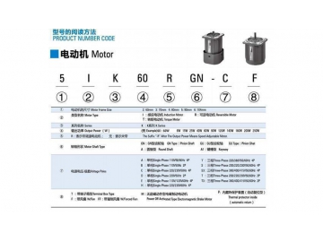
2. The controller can select speed variations between 90-1350rpm at 50Hz and 90-1650rpm at 60Hz
3. Run the motor at proper speeds to avoid overheating.
Application
These AC motors are found in a wide range of industrial production machinery, including conveying equipment, food machinery, medical machinery, printing machines, etc.
Technical Parameters
| Model Lead Wire Type | Max. Output Power | Voltage | Frequency | Speed Control Range | Permitted Torque | Starting Torque | Current | Capacitor |
| Pinion Shaft | Round Shaft | W | V | Hz | r/min | 1200r/min mN.m | 90r/min mN.m | mN.m | r/min | μF |
| 3IK15RGN-A | 3IK15RA-A | 15 | 1ph 100 | 50 | 90-1350 | 120 | 35 | 55 | 0.35 | 6 |
| 60 | 90-1650 | 0.33 |
| 3IK15RGN-E | 3IK15RA-E | 15 | 1ph 110 | 60 | 90-1650 | 125 | 35 | 55 | 0.3 | 5 |
| 1ph 120 | 0.32 |
| 3IK15RGN-C | 3IK15RA-C | 15 | 1ph 220 | 50 | 90-1350 | 120 | 35 | 54 | 0.18 | 1.2 |
| 1ph 230 | 0.2 |
| 3IK15RGN-H | 3IK15RA-H | 15 | 1ph 220 | 60 | 90-1650 | 85 | 35 | 52 | 0.16 | 1.2 |
| 1ph 230 | 105 | 55 | 0.15 |
| Model Lead Wire Type | Max. Output Power | Voltage | Frequency | Speed Control Range | Permitted Torque | Starting Torque | Current | Capacitor |
| Pinion Shaft | Round Shaft | W | V | Hz | r/min | 1200r/min mN.m | 90r/min mN.m | mN.m | r/min | μF |
| 2IK6RGN-A | 2IK6RA-A | 6 | 1ph 100 | 50 | 90-1350 | 50 | 30 | 35 | 0.24 | 3.5 |
| 60 | 90-1650 | 50 | 29 | 35 | 0.25 |
| 2IK6RGN-E | 2IK6RA-E | 6 | 1ph 110 | 60 | 90-1650 | 50 | 29 | 30 | 0.16 | 2 |
| 1ph 120 | 0.18 |
| 2IK6RGN-C | 2IK6RA-C | 6 | 1ph 220 | 50 | 90-1350 | 55 | 29 | 35 | 0.13 | 0.8 |
| 1ph 230 | 0.11 |
| 2IK6RGN-H | 2IK6RA-H | 6 | 1ph 220 | 60 | 90-1650 | 55 | 29 | 35 | 0.14 | 0.8 |
| 1ph 230 | 0.12 |
| Model Lead Wire Type | Max. Output Power | Voltage | Frequency | Speed Control Range | Permitted Torque | Starting Torque | Current | Capacitor |
| Pinion Shaft | Round Shaft | W | V | Hz | r/min | 1200r/min mN.m | 90r/min mN.m | mN.m | r/min | μF |
| 4IK25RGN-A | 4IK25RA-A | 25 | 1ph 100 | 50 | 90-1350 | 190 | 47 | 88 | 0.5 | 8 |
| 60 | 90-1650 | 0.55 |
| 4IK25RGN-E | 4IK25RA-E | 25 | 1ph 110 | 60 | 90-1650 | 190 | 50 | 108 | 0.45 | 7 |
| 1ph 120 | 0.5 |
| 4IK25RGN-C | 4IK25RA-C | 25 | 1ph 220 | 50 | 90-1350 | 190 | 47 | 88 | 0.25 | 1.8 |
| 1ph 230 | 0.23 |
| 4IK25RGN-H | 4IK25RA-H | 25 | 1ph 220 | 60 | 90-1650 | 190 | 45 | 88 | 0.23 | 1.8 |
| 1ph 230 |
| Model Lead Wire Type | Max. Output Power | Voltage | Frequency | Speed Control Range | Permitted Torque | Starting Torque | Current | Capacitor |
| Pinion Shaft | Round Shaft | W | V | Hz | r/min | 1200r/min mN.m | 90r/min mN.m | mN.m | r/min | μF |
| 5IK40RGN-A | 5IK40RA-A | 40 | 1ph 100 | 50 | 90-1350 | 260 | 70 | 180 | 0.65 | 12 |
| 60 | 90-1650 | 0.7 |
| 5IK40RGN-E | 5IK40RA-E | 40 | 1ph 110 | 60 | 90-1650 | 260 | 65 | 180 | 0.55 | 8 |
| 1ph 120 | 0.6 |
| 5IK40RGN-C | 5IK40RA-C | 40 | 1ph 220 | 50 | 90-1350 | 300 | 75 | 160 | 0.35 | 2.5 |
| 1ph 230 | 0.4 |
| 5IK40RGN-H | 5IK40RA-H | 40 | 1ph 220 | 60 | 90-1650 | 230 | 70 | 145 | 0.35 | 2.5 |
| 1ph 230 | 0.4 |
| Model Lead Wire Type | Max. Output Power | Voltage | Frequency | Speed Control Range | Permitted Torque | Starting Torque | Current | Capacitor |
| Pinion Shaft | Round Shaft | W | V | Hz | r/min | 1200r/min mN.m | 90r/min mN.m | mN.m | r/min | μF |
| 5IK60RGN-AF | 5IK60RA-AF | 60 | 1ph 100 | 50 | 90-1350 | 460 | 140 | 265 | 1 | 20 |
| 60 | 90-1650 | 490 | 160 | 1.1 |
| 5IK60RGN-EF | 5IK60RA-EF | 60 | 1ph 110 | 60 | 90-1650 | 490 | 160 | 265 | 0.8 | 12 |
| 1ph 120 | 0.85 |
| 5IK60RGN-CF | 5IK60RA-CF | 60 | 1ph 220 | 50 | 90-1350 | 490 | 140 | 265 | 0.5 | 4 |
| 1ph 230 | 0.55 |
| 5IK60RGN-HF | 5IK60RA-HF | 60 | 1ph 220 | 60 | 90-1650 | 490 | 160 | 265 | 0.5 | 4 |
| 1ph 230 | 0.55 |
| Model Lead Wire Type | Max. Output Power | Voltage | Frequency | Speed Control Range | Permitted Torque | Starting Torque | Current | Capacitor |
| Pinion Shaft | Round Shaft | W | V | Hz | r/min | 1200r/min mN.m | 90r/min mN.m | mN.m | r/min | μF |
| 5IK90RGU-AF | 5IK90RA-AF | 90 | 1ph 100 | 50 | 90-1350 | 710 | 230 | 405 | 1.55 | 25 |
| 60 | 90-1650 | 260 | 1.85 |
| 5IK90RGU-EF | 5IK90RA-EF | 90 | 1ph 110 | 60 | 90-1650 | 710 | 260 | 410 | 1.4 | 20 |
| 1ph 120 | 1.45 |
| 5IK90RGU-CF | 5IK90RA-CF | 90 | 1ph 220 | 50 | 90-1350 | 710 | 230 | 410 | 0.72 | 5 |
| 1ph 230 | 0.7 |
| 5IK90RGU-HF | 5IK90RA-HF | 90 | 1ph 220 | 60 | 90-1650 | 710 | 260 | 410 | 0.71 | 5 |
| 1ph 230 | 0.75 |
| Model Lead Wire Type | Max. Output Power | Voltage | Frequency | Speed Control Range | Permitted Torque | Starting Torque | Current | Capacitor |
| Pinion Shaft | Round Shaft | W | V | Hz | r/min | 1200r/min mN.m | 90r/min mN.m | mN.m | r/min | μF |
| 5IK120RGU-AF | 5IK120RA-AF | 120 | 1ph 100 | 50 | 90-1350 | 750 | 360 | 530 | 2.1 | 30 |
| 60 | 90-1650 | 2.5 |
| 5IK120RGU-EF | 5IK120RA-EF | 120 | 1ph 110 | 60 | 90-1650 | 750 | 360 | 530 | 1.65 | 25 |
| 1ph 120 | 1.8 |
| 5IK120RGU-CF | 5IK120RA-CF | 120 | 1ph 220 | 50 | 90-1350 | 750 | 360 | 530 | 1 | 7 |
| 1ph 230 | 0.95 |
| 5IK120RGU-HF | 5IK120RA-HF | 120 | 1ph 220 | 60 | 90-1650 | 750 | 360 | 530 | 1 | 7 |
| 1ph 230 | 0.95 |
| Model Lead Wire Type | Max. Output Power | Voltage | Frequency | Speed Control Range | Permitted Torque | Starting Torque | Current | Capacitor |
| Pinion Shaft | Round Shaft | W | V | Hz | r/min | 1200r/min mN.m | 90r/min mN.m | mN.m | r/min | μF |
| 6IK120RGU-AF | 6IK120RA-AF | 120 | 1ph 100 | 50 | 90-1350 | 750 | 360 | 530 | 2.1 | 30 |
| 60 | 90-1650 | 2.5 |
| 6IK120RGU-EF | 6IK120RA-EF | 120 | 1ph 110 | 60 | 90-1650 | 750 | 360 | 520 | 1.7 | 20 |
| 1ph 120 | 1.8 |
| 6IK120RGU-CF | 6IK120RA-CF | 120 | 1ph 220 | 50 | 90-1350 | 750 | 330 | 530 | 0.95 | 8 |
| 1ph 230 |
| 6IK120RGU-HF | 6IK120RA-HF | 120 | 1ph 220 | 60 | 90-1650 | 750 | 360 | 530 | 0.95 | 8 |
| 1ph 230 | 1 |
| Model Lead Wire Type | Max. Output Power | Voltage | Frequency | Speed Control Range | Permitted Torque | Starting Torque | Current | Capacitor |
| Pinion Shaft | Round Shaft | W | V | Hz | r/min | 1200r/min mN.m | 90r/min mN.m | mN.m | r/min | μF |
| 6IK140RGU-AF | 6IK140RA-AF | 140 | 1ph 100 | 50 | 90-1350 | 830 | 420 | 620 | 2.7 | 35 |
| 60 | 90-1650 | 3 |
| 6IK140RGU-EF | 6IK140RA-EF | 140 | 1ph 110 | 60 | 90-1650 | 830 | 420 | 620 | 1.8 | 25 |
| 1ph 120 | 1.95 |
| 6IK140RGU-CF | 6IK140RA-CF | 140 | 1ph 220 | 50 | 90-1350 | 830 | 420 | 620 | 1.05 | 10 |
| 1ph 230 | 1.15 |
| 6IK140RGU-HF | 6IK140RA-HF | 140 | 1ph 220 | 60 | 90-1650 | 830 | 420 | 620 | 1.05 | 10 |
| 1ph 230 | 1.15 |
| Model Lead Wire Type | Max. Output Power | Voltage | Frequency | Speed Control Range | Permitted Torque | Starting Torque | Current | Capacitor |
| Pinion Shaft | Round Shaft | W | V | Hz | r/min | 1200r/min mN.m | 90r/min mN.m | mN.m | r/min | μF |
| 6IK200RGU-CF | 6IK200RA-CF | 200 | 1ph 220 | 50 | 90-1350 | 920 | 500 | 1000 | 1.4 | 10 |
| 1ph 230 |
| 6IK200RGU-HF | 6IK200RA-HF | 200 | 1ph 220 | 60 | 90-1650 | 920 | 500 | 1000 | 1.4 | 10 |
| 1ph 230 |
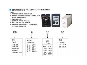
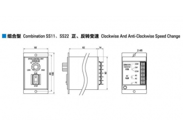
| Model | Voltage(V) | Frequency(Hz) | Max.Current(A) | Motor Power (W) | Speed Range(r/min) | Speed Changer | Speed Responder | Speed Stability | Working Temperature |
| US11 | 110V±10% | 50/60 | 5 | 6~140 | 9/1350 | 3% | (0.5) | Excellent | minus10℃~+50℃ |
| US22 | 220V±10% | 6~200 | 9/1650 |
| US11 | 110V±10% | 50/60 | 5 | 6~140 | 9/1350 | 3% | (0.5) | Excellent | minus10℃~+50℃ |
| US22 | 220V±10% | 6~200 | 9/1650 |
| US33 | 110V±10% | 50/60 | 5 | 6~140 | 9/1350 | 3% | (0.5) | Excellent | minus10℃~+50℃ |
| 220V±10% | 6~200 | 9/1650 |
Features
1. Aluminum radiation plate: good radiating efficiency.
2. Motor includes a stator and rotor, there is a repulsion force which drives the motor by magnetic field.
3. The output shaft: shaft with gears can match with a gearbox to reduce speed, the round shaft can connect with various types of couplings.
4. Wire: connect to the power supply, this wire can be lengthened as requested.
Model Selection Factors
1. Please specify the power of motor: we have 6W-250W options for micro gear motor.
2. General Voltage: Single phase 110V, 220V, 100V 50Hz/60Hz; Three phase 220V, 380V 50Hz/60Hz
3. Frame size of motor: 60*60mm. 70*70mm, 80*80mm, 90*90mm, 104*104mm
4. Poles of motor: 2P, 4P,6P, 8P
5. Ratio: Ratio of gearbox--your required output speed for motor/rated motor speed
6. The gearbox frame size must be same with size of motor
This motor can rotate at clockwise and counter clockwise. For single phase motor, please change the rotate direction after motor stop.
Installation
1. Center the central axis when installing the gear motor. Error should not be greater than the compensation value of the coupler. A proper centering can extend the service life and maximize transmission efficiency.
2. Do not knock the motor when mounting the driving medium on the output shaft. We suggest using the assembly fixture and inner thread of the shaft and bolt to press the driving medium.
3. The gear motor should be tightly mounted on a stable horizontal base to make sure that the oil can be drained properly and to allow cool air to circulate freely. This helps prevent noise and vibration.
4. The mounting unit allows workers access to the oil pointer, breather plug and oil drain plug with great convenience. After moving the gear motor in place, inspect the compaction reliability of each fastener for a proper fit. The motor is lubricated with oil grease. Replace the screw plug with a breather plug prior to operating.
Note: After a certain time running of the gear motor, regularly check the gearbox oil level to avoid possible leakage caused by the motor shell. For example, overflowing or higher than suggested working temperatures will affect the usage of the gear motor. So different gear motors will be selected according to different temperatures.
How to store the reducer?
1) Keep the reducer in a clean dry place.
2) If it will be stored outdoor or in a humid place, please put the reducer in a box and pack it tightly with a plastic bag to avoid rain exposure and external erosion.
Cautions during Operation
1) Overload should be avoided.
2) Input speed cannot exceed the proper max. speed.
3) Please stop and check the reducer if any of the following occurs:
Sudden temperature rise
Abnormal noise
Unstable speed
4) Please change the motor shaft direction after stopping the motor.
Warranty Instruction
The following costs and damages are not included in our warranty:
1) Freight cost
2) If the reducer connects with or inserts into a unit during dismounting or mounting, or any other extra action, there will be a cost as this is not in the warranty.
3) Other accompanying unspecified damage.
Download
Related Names
Gear motor, geared motor, ac gear motor, ac geared motor, ac adjustable speed motor, speed adjusting gear motor, speed adjusting geared motor, speed controlled gear motor, speed controlled geared motor