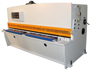
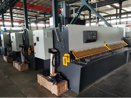
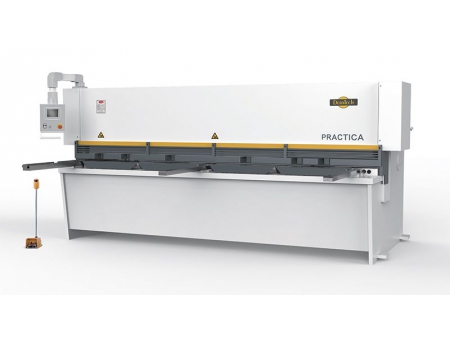
Hydraulic Swing Beam Shear
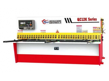
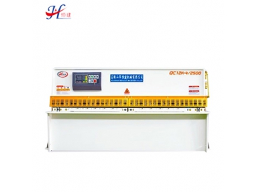
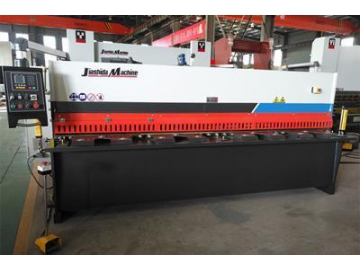
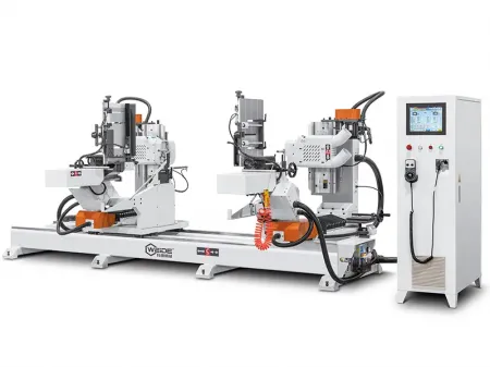
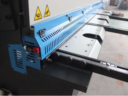
This QC series hydraulic swing beam shear is equipped with Schneider electrical system, back gauge attached with encoder and NC system, this swing beam shearing machine enjoys much higher precision and could display the exact position of the back gauge. It could be used for shearing sheet metals of the maximum width of 6000mm and maximum thickness of 20mm. Therefore, this sheet metal cutting equipment has been used in various metal processing workshops since its first appearance into the market.
Control System of Hydraulic Swing Beam Shear1. Fine Adjustment Screw
2. Feeder Balls
3. Upper Blade Carrier
4. Small Gear
5. Fan-shaped Device
6. Upper Limit Travel Switch
7. Eccentric Support Device
8. Support Shaft
9. Lower Limit Travel Switch
10. Pressure Gauge Switch
11. Pressure Gauge
12. Valve Block
13. Oil Level Gauge
14. Electromagnetic Relief Valve
15. Adjustment Knob
This DAC-360 control system, designed based on the classic controller in the international market, is a quality controlling device geared to the shearing machine tools in China. Adopting a unique drive control technique, this automatic controller could not only promotes the shearing precision but also reduce the operation cost. Given this, it has laid a foundation for the wide application of sheet metal guillotine shearing machine in China.
1. Position control of back gauge;
2. Single-side and double-side positioning, effectively eliminating the gap between ball screws;
3. Retraction function;
4. Automatic search of reference point;
5. Power-down memorization and protection of specifications, positions and processes;
6. Instruction function;
7. Memory capacity: 40 programs and 25(maximum) for each;
8. Manual operation(before the specification being set)。
9. Two control methods for back gauge control: servo motor control or frequency control;
10.F function;
11. Shearing stroke control.
Features of Hydraulic Swing Beam Shear
1. This sheet metal shearing machine adopts an integrated welded steel rack which has gone the vibration stress relief treatment. Therefore, it enjoys high rigidity, operation precision and excellent precision retaining ability.
2. Adopting the hydraulic transmission and nitrogen return, this hydraulic swing beam shear allows users to adjust the blade gap by only turning the hand wheel. The blade gap equals to the thickness of the plate which is shown on the form.
3. This sheet metal forming machine is equipped with a movable blade bearing and four-edge blades. This design could not make it convenient for users to adjust the blade gap, promoting the cutting precision, but also extend the blades’ service life.
4. The tandem cylinder synchronizing system of this hydraulic shearing machine could ensure uniform pressure on the machine tool.
5. The motorized back gauge and electrical counter of this sheet metal shear make it easier for users to adjust the position of back gauge.
6. The hydraulic pressure feeder promotes the cutting precision of this metalworking shear.
7. The ball bearing retainer and retainer bar make it easier for users to operate the machine.
8. This hydraulic shear operates smoothly with low noise.
Main Configuration of Hydraulic Swing Beam Shear
1. Hydraulic system provided by a reliable Chinese supplier(China)(systems provided by other internal supplier such as Atos are also available);
2. Electrical system provided by Schneider Electric in France;
3. Gear pump provided by Chengjie (China)(devices provided by other foreign suppliers are also available for users, such as that provided by Sumitomo);
4. main motor provided by Shuangta(China)( devices provided by other foreign suppliers are also available for users, such as that provided by Siemens);
5. E200 NC system provided by Estum(China)( devices provided by other foreign suppliers are also available for users, such as the control system provided by DELEM);
6. Ball screws and linear guideways provided by Taiwan suppliers.
| Model | Thickness of sheet metal | Width of sheet metal | Number of stroke | Back gauge range | Shear angle | Throat depth | Power of main motor | Dimension |
| (mm) | (mm) | ( per min) | (mm) | (。) | (mm) | (kW) | L×W×H(mm) | |
| 4 | 2500 | ≥18 | 600 | 1.5 | 100 | 5.5 | 3040×1550×1550 | |
| 4 | 3200 | ≥16 | 600 | 1.5 | 100 | 5.5 | 3840×1600×1650 | |
| 4 | 4000 | ≥12 | 600 | 1.5 | 100 | 7.5 | 4640×1700×1700 | |
| 6 | 2500 | ≥15 | 600 | 1.5 | 100 | 7.5 | 3050×1710×1620 | |
| 6 | 3200 | ≥13 | 600 | 1.5 | 100 | 7.5 | 3750×1710×1620 | |
| 6 | 4000 | ≥10 | 600 | 1.5 | 100 | 7.5 | 4550×1850×1700 | |
| 6 | 6000 | ≥6 | 600 | 1.5 | 100 | 11 | 6480×2100×2300 | |
| 8 | 2500 | ≥14 | 600 | 1.5 | 100 | 7.5 | 3060×1710×1620 | |
| 8 | 3200 | ≥12 | 600 | 1.5 | 100 | 7.5 | 3760×1710×1620 | |
| 8 | 4000 | ≥10 | 600 | 1.5 | 100 | 11 | 4560×1850×1700 | |
| 8 | 6000 | ≥6 | 600 | 1.5 | 100 | 15 | 6490×2100×2300 | |
| 10 | 2500 | ≥12 | 600 | 1.5 | 100 | 11 | 3080×1800×1700 | |
| 10 | 3200 | ≥10 | 600 | 1.5 | 100 | 11 | 3780×1800×1700 | |
| 10 | 4000 | ≥8 | 600 | 1.5 | 100 | 11 | 4580×2100×2000 | |
| 10 | 6000 | ≥5 | 600 | 1.5 | 100 | 15 | 6580×2300×2300 | |
| 12 | 2500 | ≥10 | 800 | 2 | 100 | 18.5 | 3140×2050×2000 | |
| 12 | 3200 | ≥8 | 800 | 2 | 100 | 18.5 | 3840×2150×2000 | |
| 12 | 4000 | ≥6 | 800 | 2 | 100 | 18.5 | 4680×2150×2100 | |
| 12 | 6000 | ≥4 | 800 | 2 | 100 | 22 | 6900×2600×2700 | |
| 16 | 2500 | ≥8 | 800 | 2 | 100 | 18.5 | 3160×2050×2000 | |
| 16 | 3200 | ≥7 | 800 | 2 | 100 | 18.5 | 3860×2150×2000 | |
| 16 | 4000 | ≥6 | 800 | 2 | 100 | 18.5 | 4700×2150×2100 | |
| 16 | 6000 | ≥4 | 800 | 2 | 100 | 22 | 6920×2600×2700 | |
| 20 | 2500 | ≥7 | 800 | 2.5 | 100 | 22 | 3440×2300×2500 | |
| 20 | 3200 | ≥6 | 800 | 2.5 | 100 | 22 | 4140×2350×2700 | |
| 20 | 4000 | ≥5 | 800 | 2.5 | 100 | 22 | 4940×2600×2900 |
Please not that: the above parameters are subject to change without notice.


