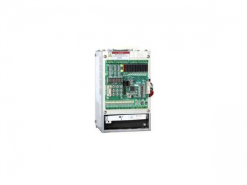
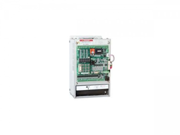
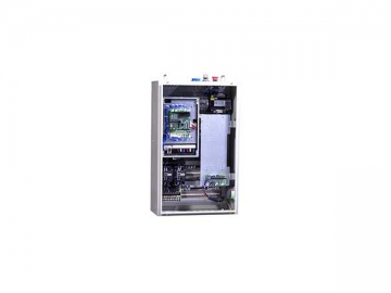
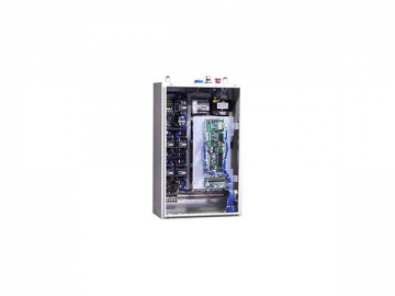
Escalator Integrated Drive and Controller
As its name indicates, AS330 escalator integrated drive and controller is a combination of an escalator drive and an escalator controller. It comes with anti-interference capability and design exceeding the highest industrial design standard, and features compact structure, small size, few wire connection, and high reliability. It is also easy for operation and economical.
With functions of both escalator controller and escalator drive, the escalator integrated drive and controller provides escalators very high safety standard, and meanwhile, it can also offers multiple escalator operation control functions to suit customers' demands. Additionally, it allows the escalator to operate in different speeds according to passenger flow, thus helping saving energy.
The escalator integrated drive and controller is composed of a motor drive circuit, power supply circuit, and control circuit. The control circuit of the escalator integrated drive and controller functions to receive the signal and then sends the signal to motor drive circuit. The motor drive circuit also receives power supply signals from both industrial power supply and escalator drive's output power supply, and sends signals to control the escalator traction machine.
With the escalator integrated drive and controller, the escalator working process is divided into two parts. When the escalator is in speed changing or standby status, it is powered by the escalator drive output power supply, and when it is in smooth operation status, it is powered by industrial power supply. The escalator integrated drive and controller ensure escalators have compact structure, convenience installation, simple testing and commissioning, highly effective operation and high safety, etc.
Technical Characteristics and Functions of the Escalator Integrated Drive and Controller
1. The escalator integrated drive and controller is designed with dual 32-bit embedded microprocessors to control escalator operation and electric motor drive.
2. Through making improvement on the equipment hardware, our escalator integrated drive and controller comes with a maximum junction temperature of 175℃, low switch loss and extended service life.
3. The escalator integrated drive and controller provides escalators with variable frequency control and industrial frequency control. To illustrate, it offers fully variable frequency control, bypass variable frequency control, Y-△ control modes to suit customers' varied demands and reduce escalator failure rate. When the escalator is in standby and speed-changing status, it is variable frequency controlled; while in steady operation status, it is industrial frequency controlled. Thus, energy consumption can be reduced.
4. Designed based on new PWM dead time compensation technology, the escalator integrated drive and controller is able to ensure reduced motor noise and loss. Meanwhile, the adoption of dynamic PWM carrier modulation technology also helps reduce motor operation noise.
Main Features
1. Closed loop vector control for higher performance.
2. New PWM dead-zone compensation technology leads to less energy loss.
3. Dynamic PWM carrier modulation technology reduces motor noise.
4. Smart running speed controller of the escalator integrated drive and controller for energy conservation.
5. Dual 32-bit embedded microprocessor.
6. Bypass frequency conversion technology.
7. Redundancy control of frequency conversion and power frequency.
AS330 Yürüyen Merdiven Tümleşik Sürücü ve Denetleyici Modeli Listesi
| Model AS330- | Rated capacity (kVA) | Rated output current (A) | Applicable motor (kW) |
| 4T05P5 | 8.5 | 13 | 5.5 |
| 4T07P5 | 14 | 18 | 7.5 |
| 4T0011 | 18 | 27 | 11 |
| 4T0015 | 24 | 34 | 15 |
| 4T18P5 | 29 | 41 | 18.5 |
| 4T0022 | 34 | 48 | 22 |
| 4T0030 | 50 | 65 | 30 |
| 4T0037 | 61 | 80 | 37 |
Technical Specifications of the Escalator Integrated Drive and Controller
| Model | 4T05P5 | 4T07P5 | 4T0011 | 4T0015 | 4T0018 | 4T0022 | 4T0030 | 4T0037 | |
| Maximum applicable motor capacity (kw) | 5.5 | 7.5 | 11 | 15 | 15.5 | 22 | 30 | 37 | |
| Rated output | Rated capacity (kVA) | 5.5 | 14 | 18 | 24 | 29 | 34 | 50 | 61 |
| Rated current (A) | 13 | 18 | 27 | 34 | 41 | 48 | 65 | 80 | |
| Maximum voltage output (V) | 400V-class: 3-Phase, 380/400/415/440/460V (Corresponding to the input voltage) | ||||||||
| Input Power | Phase, voltage, frequency | 400V-class: 3-Phase, 380/400/415/440/460V, 50/60Hz | |||||||
| Allowed fluctuation in voltage | -15%-- 10% | ||||||||
| Allowed fluctuation in frequency | -5%-- 5% | ||||||||
| Instantaneous voltage drop | 400v-class: Keep running when voltage is above AC300V; Under-voltage protection is available in 15ms when the voltage is below AC 300V. | ||||||||
| Drive Characteristics | Control Type | Escalator control mode | |||||||
| Starting torque | 180%/0.5Hz | ||||||||
| Speed control range | 1:100 | ||||||||
| Speed control precision | ±0.5 | ||||||||
| Torque limitation | Available (adjustable with parameter) | ||||||||
| Torque precision | ±5% | ||||||||
| Frequency control range | 0-120 Hz | ||||||||
| Frequency precision (temperature fluctuation) | ±0.1 | ||||||||
| Preset frequency resolution | ±0.06Hz/120Hz | ||||||||
| Output frequency resolution (calculated resolution) | 0.01Hz | ||||||||
| Over-load capacity | 150% at zero speed, 160% < 3Hz, 200% > 3Hz | ||||||||
| Brake torque | 150% (external connected brake resistor), internal brake unit | ||||||||
| Acceleration/Deceleration time | 0.01---600s | ||||||||
| Carrier frequency | 2-11 kHz | ||||||||
| Control input/output signal | Power supply for opto-isolator input control | Isolated 24V DC | |||||||
| Power supply for Relay-output control | Isolated 24V DC | ||||||||
| Opto-isolated low-voltage input | 20-channel, switching value input, opto-isolated control signal is isolated 24VDC power supply input signal | ||||||||
| Opto-isolated high-voltage input | 1-channel, switching value input | ||||||||
| Programmable relay output 1 | 8-channel, normally open contact, SPST Contact resistance, 3A 250VAC or 3A 30VDC | ||||||||
| Programmable relay output 2 | 4-channel, NC contact, SPST Contact resistance: 6A250VDC | ||||||||
| CAN communication signal | 1-channel (safety switching monitoring) | ||||||||
| Analog input | 1-channel, single-ended or differential input, input voltage range: -10V- 10V, precision 0.1% | ||||||||
| Protection functions | Motor overload protection | The function is available through parameter setting | |||||||
| Drive overload protection | 160%, < 0Hz: 5s, 165% > 0Hz: 10s | ||||||||
| Short circuit protection | Protection for the escalator integrated drive and controller when there is over-current caused by short circuit of any two phases at the output side | ||||||||
| Input phase loss protection during operation | During the operation, if there is input phase loss, output is stopped to protect the escalator integrated drive and controller | ||||||||
| Phase-loss protection | When one phase is lost during escalator operation, the circuit will be switched off to protect the integrated escalator inverter and controller | ||||||||
| Over-voltage threshold | 810V(400V series) | ||||||||
| Under-voltage threshold | 380V(400V series) | ||||||||
| Instantaneous power off compensation | Protection over 15s | ||||||||
| Over-heating of radiation fins | Protection through thermistor | ||||||||
| Braking unit protection | Automatic diagnosis of braking unit failures, and then give protections | ||||||||
| Module protection | Include overcurrent, short circuit and overheat protections | ||||||||
| Current sensor protection | Auto detect when powered on | ||||||||
| Reversed-speed protection | Detected by photoelectric switch | ||||||||
| I ²t protection | Detect through 3-phase current | ||||||||
| Over-high input voltage protection | 400V series: protection is available when voltage is > 725V, 200V series: protection is available when voltage is > 360V Detect when stopped. | ||||||||
| Output ground fault protection | If there is any short circuit to ground during operation, the output will be stopped to protect the elevator inverter | ||||||||
| Output unbalance protection | If there is unbalanced output current, the output will be stopped to protect the elevator inverter | ||||||||
| Braking resistor short circuit protection | Detect while braking | ||||||||
| Anti-reversal protection | Detected in the operation of the escalator reversal run protection | ||||||||
| Over-speed protection | When speed is over 100% of rated speed | ||||||||
| Under-speed protection | When operation speed far less than the rated speed resulting from errors, etc. | ||||||||
| Handrail speed detection protection | Protection is available when inconsistent handrail speed is detected during escalator operation | ||||||||
| Stair-loss protection | Check out the stair-loss during operation, and activate protection | ||||||||
| EEPROM fault | Self-detect when powered on | ||||||||
| Working Environment | Chinese/English LCD display | All sub-menus | |||||||
| Ambient temp. | -10- 45℃ | ||||||||
| Humidity | Below 95%RH (no condensation) | ||||||||
| Storage temps. | -20- 60℃ (for short-term transportation) | ||||||||
| Application places | Indoor (without corrosive gas and heavy dust) | ||||||||
| Altitude | Below 1000m | ||||||||
| Structure | Protection degree | IP20 | |||||||
| Cooling method | Air-blast cooling | ||||||||
STEP is an escalator integrated drive and controller manufacturer in China. We provide a variety of products, including high voltage inverter, indicator board, elevator group control system, elevator button, and more.
