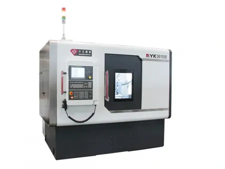
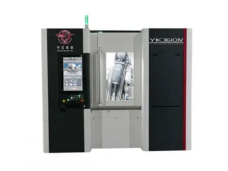
CNC Horizontal Gear Hobbing Machine


Request a Quote
- Max. working diameter (mm): ∅100
- Max.working module (mm): 3
- Max. Workpiece Diameter spindle speed (r/min): 1000
- Max. hob spindle speed (r/min): 6000
- Hob shifting length (Y-axis) (mm): 100
- Z-axis travel (mm): 280
- Hob head swing angle (°): ±45
- Min. tooth number (teeth): 3
- Max. hob size (diameter×length) (mm): ∅80×110
- Total power (kVA): 25
- Overall dimensions (L×W×H) (mm): 3490×3370×2380
- Machine weight (t): 6
- Max. working diameter (mm): ∅100
- Max.working module (mm): 3
- Max. Workpiece Diameter spindle speed (r/min): 600
- Max. hob spindle speed (r/min): 4000
- Hob shifting length (Y-axis) (mm): 100
- Z-axis travel (mm): 280
- Hob head swing angle (°): ±45
- Min. tooth number (teeth): 3
- Max. hob size (diameter×length) (mm): ∅80×110
- Total power (kVA): 30
- Overall dimensions (L×W×H) (mm): 3530×3480×2550
- Machine weight (t): 6
Features
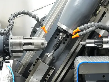
- All models in this series work with a seven-axis structure and four-axis interpolation in a horizontal layout, giving the system enough control and rigidity for precision gear cutting.
- The CNC horizontal gear hobbing machines in this series include two spindle configurations. The 3610III uses built-in motor spindles for both the hob and the workpiece, combined with temperature-controlled cooling and Heidenhain closed-loop feedback to maintain accuracy. The 3610IV pairs a servo-driven hob spindle with a built-in torque motor on the workpiece side, supported by temperature-controlled cooling and rotary-scale closed-loop control. Both designs provide stable cutting conditions during long machining cycles.
- The X and Z axes use precision ball screws and roller-type linear guides, which help keep positioning accurate and the machine rigid during cutting.
- The Y-axis uses a servo-driven cutter-shift mechanism that moves the tool precisely so the cutting edge wears more evenly, extending tool life.
- The series can machine a wide range of parts, including cylindrical gears, worm wheels, sprockets, timing-belt pulleys, flexsplines and splined shafts.
- The integrated gear-machining software supports parametric programming, lead modification and micro-compensation functions through an easy-to-use interface.
- An optional secondary tool station is available for finishing after heat treatment when tighter tolerances are required.
Sample Display
Drive gear
Power tool gears
Power tool gears
Electrode gears
Drive splines
Robot gears
Automotive gears
Drive worm shafts
Technical Specifications
| Model | | |
| Max. working diameter (mm) | ∅100 | ∅100 |
| Max.working module (mm) | 3 | 3 |
| Max. Workpiece Diameter spindle speed (r/min) | 1000 | 600 |
| Max. hob spindle speed (r/min) | 6000 | 4000 |
| Hob shifting length (Y-axis) (mm) | 100 | 100 |
| Z-axis travel (mm) | 280 | 280 |
| Hob head swing angle (°) | ±45 | ±45 |
| Min. tooth number (teeth) | 3 | 3 |
| Max. hob size (diameter×length) (mm) | ∅80×110 | ∅80×110 |
| Total power (kVA) | 25 | 30 |
| Overall dimensions (L×W×H) (mm) | 3490×3370×2380 | 3530×3480×2550 |
| Machine weight (t) | 6 | 6 |
Standard Components
FANUC 0i-MF Plus CNC system
Magnetic roller chip conveyor, mounted on the coolant tank and suitable for ferrous, magnetizable chips
Oil chiller for cooling the spindle motor
Hob arbor for mounting and positioning the hobbing cutter
Optional Configurations
Automated loading and unloading units can be added to handle shaft-type and disk-type gears, allowing continuous machining without manual intervention.
A secondary-tool station can be configured to perform post-cutting operations, such as deburring or light finishing, after the gear teeth are formed.
An optional deburring unit can remove burrs from the workpiece end face directly within the machining process.