Three-Row Cylindrical Roller Slewing Bearings
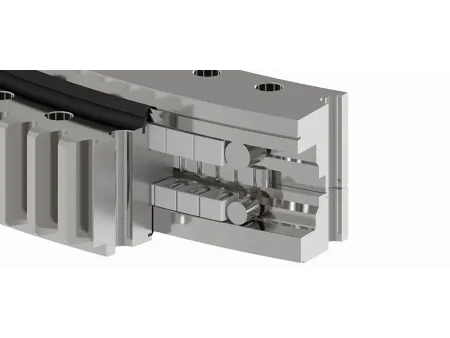
Three-row cylindrical roller slewing bearings is built for applications requiring exceptional load-handling capabilities. With three rows of rollers, this bearing design ensures that the load is distributed across different rows, each dedicated to managing specific force such as axial loads, radial loads, and overturning moments. This configuration provides superior rigidity and stability during rotation, making it highly effective for heavy-duty and complex load scenarios. However, due to its design, it requires precise installation and is more sensitive to any deformations in the mounting structure.
These bearings are typically manufactured using 42CrMo4 steel with induction-hardened raceways to maximize durability. However, depending on the application and customer needs, other materials can be selected to suit specific operational environments.
LYXQL has advanced capabilities in producing Three-row cylindrical roller slewing bearings, tailored to meet demanding industrial requirements. We can manufacture integrated structure bearings with a maximum outer diameter of 12 meters, while for split structures, the maximum outer diameter reaches up to 20 meters.
The gear module size can go up to 45mm, accommodating a wide range of design needs.
(We offer customization options to create non-standard products based on specific user requirements)
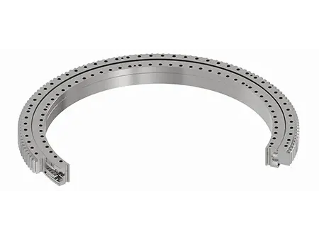
Our three-row cylindrical roller slewing bearings are designed to be versatile, available in three distinct configurations: external gear, internal gear, and gearless designs. Each option is built with a robust structure that includes inner and outer rings, rollers, spacers (bearing cages), and seals. To further enhance durability, especially in challenging environments, we offer additional dust-proofing features like dust covers or ash shields based on specific application requirements.
This design features gear teeth on the outer ring. Due to the external location of the gear mesh, this configuration generally requires more installation space compared to internal gear designs. It is ideal for applications where external gear interaction is necessary and where space constraints are not a primary concern.
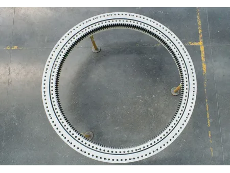
In this configuration, the gear teeth are located on the inner ring, allowing the gear mesh to occur inside the bearing. This design is more space-efficient than the external gear option, making it suitable for applications where installation space is limited.
This gearless design features smooth inner and outer rings with no gear teeth, making it suitable for applications where gear interaction is not needed. This simple design offers ease of maintenance and can be used in systems where simplicity and reliability are key.
What are the key advantages of Three-Row Cylindrical Roller Slewing Bearings compared to other types?
- Three Rows of Cylindrical Rollers: Precisely arranged in three separate rows, the rollers contact both inner and outer raceways to ensure optimal load distribution.
- Exceptional Load Capacity: Capable of handling high radial, axial, and tilting moment loads at the same time, these bearings are ideal for heavy-duty operations.
- Space-Efficient Design: Despite their strength, they maintain a relatively compact profile, maximizing space utilization in equipment layouts.
- Ease of Installation and Maintenance: Standardized dimensions and mounting holes enable simplified setup and long-term serviceability.
What are the typical applications of Three-Row Cylindrical Roller Slewing Bearings?
- Bucket wheel reclaimers in coal, mining, and port equipment
- Main bearings for tunnel boring machines used in metro and underground projects
- Port cranes
- Marine cranes
What are the main structural components of this type of bearing?
- Inner Ring: Serves as the primary load-carrying structure, connected to the rotating part of the equipment.
- Outer Ring: Supports the rollers and often incorporates gear teeth for rotational control.
- Three Rows of Cylindrical Rollers: Provide enhanced capacity and stability by distributing load across multiple contact points.
- Spacers: Ensure precise roller spacing and prevent contact interference.
- Cage or Retainer: Maintains roller alignment and promotes consistent movement.
- Seals and Lubrication System: Protects internal components from contamination and maintains smooth operation.
- Mounting Holes: Standardized for convenient integration into your machinery.


