Waste Rubber Pyrolysis Oil Plant

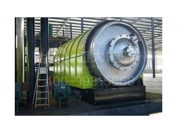
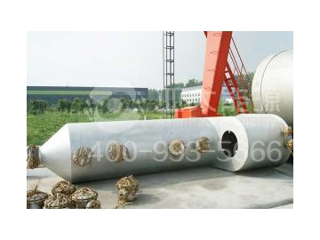

- Pyrolysis furnace
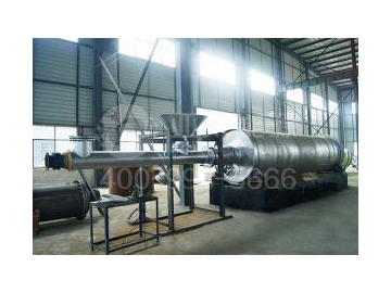
- Automatic feeding system
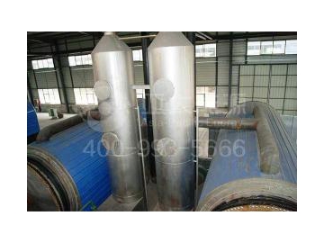
- Dedusting tower
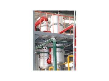
- Heat exchanger
- Nebulizing tower
Applicable raw materials and industries
Waste plastics, Waste rubber, Waste tire, Waste PMMA, Municipal solid waste, Medical waste, Oil shale
1. Main pyrolysis furnace
2. Automatic feeding and unloading system
3. Mechanical sealing system
4. Power system
5. Multifunction separation equipment
6. Straight type pipe bundle condenser
7. Oil-water separator
8. Residual oil tank
9. Micro negative pressure device
10. Water seal
11. Exhaust recovery system
12. Flue gas dedusting system
13. Power distribution cabinet
14. Water cooling tower
15. High temperature oil pump
16. Oil pump
17. Water pump
| Model | Treatment capacity in 24h | Engine speed | Power | Cooling water consumption (T/h) | Noise dB(A) | Dimension (L*W*H) | Weight (kg) |
| 12m3 | 0.4rpm | 10KW | 2 | ≤65 | 7325*1995*2535 | 14340 | |
| 25m3 | 0.4rpm | 12KW | 2 | ≤65 | 7325*2695*3235 | 21030 | |
| 30m3 | 0.4rpm | 14KW | 2 | ≤65 | 7325*3100*3640 | 24855 |
● Raw material: waste tire;
● Structure: horizontal dual drive;
● Working mode: continuous working;
● Working pressure: micro negative pressure;
● Cooling method: water cooling;
● Driving mode: gear drive;
● Heating mode: direct/hot wind;
● Installation: with foundation;
● Manufacturing cycle: 20 workdays.
The waste rubber pyrolysis oil plant adopts the following units:
1. Main pyrolysis furnace (patent number: ZL 2012 1 0206913.X): this pyrolysis furnace can be used for pyrolysis of waste tire, waste plastics, waste rubber, waste PMMA and some other materials.
2. Water circulating micro negative pressure (patent number: ZL 2012 2 0662804.4): it can prevent combustible gas leakage, thus greatly improve production safety.
3. Independently developed multifunction separation equipment (patent number: ZL 2014 2 0467359.5): the main function of the separation equipment is to remove the solid particles and liquid drops from the gas as much as possible, thus realizing gas-liquid-solid separation. This can ensure normal operation of oil refining pipelines and equipment sets.
4. Independently developed mechanical seal (patent number: ZL 2012 2 0254180.2/ZL 2013 1 0443212.2): the mechanical seal is mainly used for seal connecting between mechanical equipment and static equipment. It has sufficient plasticity and relatively high intensity. The maintenance is convenient. This seal can effectively compensate the thermal expansion and contraction caused by temperature variation between mechanical equipment and static equipment. It can also effectively prevent gas leakage and has cushioning effect.
5. Independently developed highly efficient self-cleaning condenser (patent number: ZL 2013 2 0397822.9): the condenser is an energy-saving equipment which can realize heat exchange between two or more fluids with different temperatures. The heat will be transferred from the fluid with higher temperature to the fluid with lower temperature, thus the fluid temperature can reach the specified value of the process, so that it can meet the requirements of the process. Meanwhile, it is the main equipment which can improve utilization of heat energy. This condenser has the following features: good cooling effect, compact structure, uneasy blockage, small flow resistance, easy cleaning etc. It can prevent the blockage caused by formation of dirt and scale on the pipe wall.
6. Independently developed non-condensable gas reverse flow combustion device (patent number: ZL 2012 2 0254119.8): the non-condensable gas produced in pyrolysis can be directly used as fuel for the pyrolysis furnace, thus producing large amount of heat energy. So the gas pollution can be prevented and the fuel can be saved as well.
7. The noise generated by the operation of the whole set of equipment is lower than 65 db. There is no generation of smoke and dust as well.
8. The flue dedusting system is equipped with bidirectional water flushing cyclone dedusting chamber to ensure that the flue emission meets the national emission standard.
The pyrolysis furnace, mechanical seal and multifunction separator of the waste rubber pyrolysis oil plant are all equipped with thermometer and pressure gauge, and the micro negative pressure device is also equipped with pressure gauge. All the thermometer and pressure gauge are remotely monitored besides that of the pyrolysis furnace. It will alarm automatically once there is any accident, thus ensuring production safety at all the time. This equipment and process can realize continuous feeding and unloading. Meanwhile, it adopts central electronic control system PLC as automatic monitoring, thus realizing continuous production.
Step one: the waste tire, waste plastics, waste rubber, waste PMMA, municipal solid waste, medical waste, oil shale and some other organic solid waste will be automatically transported to the stock bin by the conveyor. Then they will be sent into the pyrolysis furnace by the feeding system. The direction of the rotary main furnace is controlled by the reversible switch in the console cabinet. Then adjust the organic material distribution in the main furnace. The material quantity should be less than two thirds of the total volume. Shut the sealing door for feeding.
Step two: start up the heating system. When the temperature reaches about 150℃, some gases are begin to be produced (most of the gases are flue gas at this time); when the temperature reaches about 220℃, the oil gas start to enter the multifunction separator which can separate the residual oil from the oil gas and then store it in the residual oil tank through oil pipeline. The residual oil will be pumped into the pyrolysis furnace for further pyrolysis. While the oil gas will enter the cooling system after the multifunction separator. The condensed liquid oil will enter the oil-liquid separator through pipelines for oil-liquid separate measurement.
Step three: w type water-jet pump vacuates the buffer tank. Noncendensable gas will enter the micro negative pressure device through cooling pipelines under the function of negative pressure. The noncondensable gas passes through vacuum pump, primary water seal, secondary water seal and flame arrester. It will finally enter the combustion chamber of the furnace for combustion.
Step four: the flue gas produced during the pyrolysis will enter the flue gas desulphurization and dedusting equipment through flue pipe for spray dedusting and cooling. Then it will be discharged into the flue gas purifier by induced draft fan, thus realizing harmless emission finally.
Step five: the carbon black generated by the pyrolysis of waste tire, waste plastics, waste rubber, waste PMMA, municipal solid waste, medical waste, oil shale and some other organic solid waste will enter the transportation system through fully sealed crooked bellows. Then it will enter the sealed stock bin for automatic unloading. It will be store in the production workshop of carbon black at last.
Step six: this process will carry out recovery, grinding, activating, prilling of carbon black, thus producing ECO carbon black with high value-added which meets the national standard. The circulating water of the cooling system is provided by the cooling pond; the water of water seal, water tank of the vacuum pump and the dedusting tower is provided by the pump house. The water can be replenished under manual control during the system operation because the water consumption is low. The water supply and drainage of the equipment adopts cycling use of water to ensuring self circulation of water. The small amount of evaporated water is supplied by the system water.


 Solution for sorting construction waste")


")


")

 Solution for sorting municipal waste")


